
By Armin B. Burghart, Sridhar G. Iyer, and William J. Rosano, BASF Corporation
Exterior surface coatings used in many applications can be exposed for long periods of time to cyclic exposure consisting of water submersion or local water surface puddling followed by water evaporation and solar exposure. Under such conditions, several macroscopic defects can appear including blistering, adhesion loss, soil pick-up, cracking, erosion, etc. However, quite often surface microscopic film defects can start long before these macroscopic defects are visibly evident. In this article, we show surface microscopic morphology changes to coatings cycled between water (submersion) and ultraviolet (UV) exposure where both polymer and formulation compositional factors were explored. Scanning electron microscopy (SEM) showed microscopic defects such as polymer-filler separation, filler removal, and degradation and crack formation appearance after short-term (one month) cyclic testing. The micrographs also revealed that the observed film defects were confined to the exposed surface and about a few filler particle diameters deep.
Introduction
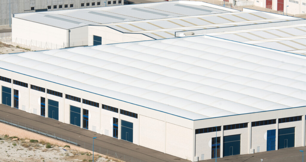
Flexible roof coatings (FRCs) are liquid-applied coatings that, when dried and cured, form a continuous, thick (ca. 20 mils) membrane over a roofing substrate, retaining flexibility at low service temperatures and high light reflectivity for reduced building energy costs. Roofing substrates include spray-applied polyurethane foam, ethylene propylene diene monomer rubber (EPDM), thermoplastic polyolefin (TPO), asphalt-based membranes, and the like. FRCs can be waterborne, solventborne, or 100% solids and are typically formulated as single-component and dual-component systems.
Around 1980, waterborne FRCs based on acrylic latex binders were introduced into the market and remain popular because of ease of application, durability, and overall cost. Since their introduction, a great deal of effort has been devoted to development of tougher films with improved water and soil resistance through latex polymer composition and process strategies. The current work focuses on single-component acrylic waterborne FRCs.
FRCs are typically applied on roofs that have very little or no slope, allowing water from rain fall, condensation, etc. to pool or pond in low-lying areas. Exposure to ponded water conditions in the exterior environment is both complex and cyclical. It is complex due to the local environmental factors, such as rain fall, rain pH, pollutants, organic matter, mildew growth, etc., and it is cyclical through factors such as temperature change, water evaporation or drainage, UV exposure, etc. Responses (degradation) to these environmental factors include blister formation, film cracking, adhesion loss, mechanical property loss, permanent plastic deformation (wrinkling), etc.
There are currently many performance standards FRCs must meet including tensile strength/elongation profiles, adhesion, water weight pick-up, water vapor permeability, soil resistance, etc. However, most property testing is performed on freshly prepared FRCs, where long-term exposure to bulk water is usually not considered. Exposure of FRCs to cyclic testing using xenon lamp exposure and water spray, or in QUV Accelerated Weathering Tester cabinets with light and condensation cycles, are common and provide a relative measure of service life, but, again, do not account for the effects of long-term exposure to bulk water.
The objective of this project is to develop a simple prototype laboratory test method to access the relative performance of several FRC types (all-acrylic) exposed to (cyclic) ponded water service conditions. The acrylic FRCs in this work develop mechanical strength primarily through coalescence of high molecular-weight latex particles and, in some cases, through cross-linking monomers.
Finally, in general, good exterior performance under high humidity or wet service conditions is a requirement across several coatings markets, including architectural, industrial, and construction coatings. It is, therefore, expected that results presented here will also provide some guidance in these market segments.
Experimental
One can envision several accelerated laboratory test approaches that account for the many exterior factors potentially affecting, in an accelerated fashion, FRC performance under external water ponding conditions. Unfortunately, accounting for all possible exterior factors and FRC experiences, even in one geographical location, for example, into a simple laboratory test would be very complex and impractical. Such environmental factors would include water submersion time, water pH and temperature, soiling, light exposure, drying and re-wetting, mildew growth, etc.
This work employs a simple approach whereby test panels coated with FRCs were cycled between water submersion and exposure to UV-A radiation. This approach is like other cyclic tests, such as ASTM 85. To account for the possibility of the removal of water-soluble and leachable formulation ingredients, fresh water was used at the beginning of each water immersion cycle. This latter aspect can be important, as removal of water-leachable materials, as well as plasticizers and coalescing aides, can affect, for example, mechanical properties of FRCs (usually by reducing elongation and increasing tensile and modulus) and subsequent water swelling. Since FRC films are bound to a substrate on one side, these changes can produce increasing internal stresses within the films, causing adhesion loss, blister formation, cracking, tearing, etc.
The testing protocol was as follows: test panels (galvanized plates, ca. 6 x 6 in.) were cleaned with acetone to remove oils and coated with two applications of the test FRCs to achieve a total dry film thickness of about 20 mils. The panels were dried under constant temperature and humidity conditions (ca. 25 oC with 50% RH) for two weeks prior to testing. In addition, a second set of coatings was prepared on release paper. These specimens were kept under constant temperature and relative humidity conditions and served as “Non-Weathered” coatings for comparison to cycled, “Weathered,” panels in microscopic imaging.
The dried panels were first placed in a QUV cabinet, using only a light mode fitted with UV-A (340 nm) bulbs and a panel temperature of 60 oC with an irradiance of 0.89 W/m2/nm at 340 nm. The distance from the bulbs to the test panels was about 8 cm. Since most binders used in FRC formulation use a photo crosslinker to provide dirt resistance, the light mode was performed before the water immersion step to allow surface photo-crosslinking to take place. After one week of UV-A exposure, the panels where examined qualitatively for color change, cracking, etc. The panels were then placed in large petri dishes (polystyrene), where deionized (DI) water was added to a height of about 0.50 in. over the panel surface. Each FRC was placed in separate petri dishes. The petri dishes were covered and placed in an oven held at 60 oC for one week. The panels were then removed from the petri dishes and again qualitatively examined for film defects (blistering adhesion loss, cracking, etc.) and allowed to dry for a few hours before being placed back into the QUV cabinet. One week of UV-A exposure, followed by one week of water exposure, was counted as one weathering cycle. A total of two cycles (total of four weeks) was performed on all FRCs.
Once cyclic testing was completed, coating surfaces were imaged using a Zeiss EVO MA 15 SEM operating in secondary electron (SE) and backscattered electron (BSE) imaging modes. The latter mode offered more contrast of surface features. Energy-dispersive X-ray spectroscopy (EDS) was performed to determine the surface elemental composition.
In addition to imaging weathered and non-weathered coating surfaces, cross-sectional imaging was performed to examine morphology changes within the bulk of the films. These specimens were prepared by cryo-ultramicrotomy and subsequently imaged using the BSE imaging mode.
Because FRCs under water-ponded conditions will likely adsorb water, it was instructive to compare surface morphology changes from cyclic testing to water weight pick-up of free-films. Water weight pick-up was measured on films cured for two weeks. Relative water weight gain for films submerged in DI water was measured as a function of time.
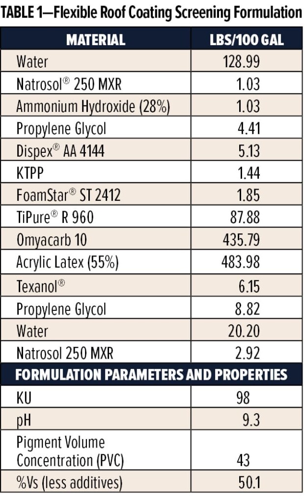
The FRCs studied included two commercially available acrylic coatings, Commercial FRC 1 and 2, and two internally formulated coatings based on acrylic latex binders synthesized at the Charlotte Technical Center. One latex-synthesized latex (Latex 1) was based on a single-stage process using a combination of acrylic and methacrylic monomers along with a few percent (based on total monomer) of acrylic acid and had a glass transition temperature (Tg ) of about -28 oC. A second synthesized latex (Latex 2) was based on a two-stage process consisting of hard and soft phases, again using a combination of acrylic and methacrylic monomers. The acid level and Tg of Latex 2 were, respectively, lower and about the same as compared to Latex 1. In addition, Latex 2 contained an ambient crosslinker. Water swelling of Latex 2 is expected to be lower than Latex 1 because the former has a more hydrophobic character, lower acid, and post-film forming crosslinking. Both latexes were formulated into FRCs using the screening formulation shown in Table 1, where the filler was CaCO3 (Omyacarb® 10).
The formulation compositions of the commercial acrylic FRCs are not known. However, surface and cross-sectional SEM and surface elemental (EDS) images (see Figures 4–5) show both coatings contained TiO2 and CaCO3 and in one formulation, also contain Al2O3. Comparison of cross-sectional SEM images of the commercial acrylic and BASF FRCs suggests qualitatively similar filler and PVC.
In addition to the previously mentioned FRC comparisons, changes to filler and dispersant type were evaluated using Latex 2 as the binder. Calcium carbonate was replaced, on an equal volume basis, with either Minex® 3 or Imsil® A30; both have about the same medium particle size (ca. 10 mm) as Omyacarb 10. Minex (Nepheline Syenite) and Imsil (Silica) are commonly used in exterior coatings formulations as they are known to have better exterior durability compared to CaCO3.
Because it is thought water adsorption is an important characteristic regarding water ponding resistance, the hydrophilic combination of the dispersants Dispex AA 4144, a poly-acid, and potassium tetra poly phosphate (KTPP) was evaluated against a more hydrophobic co-polymeric dispersant Dispex CX-4231. The level of dispersant was kept constant at about 0.66% on filler and TiO2 mass.
Results
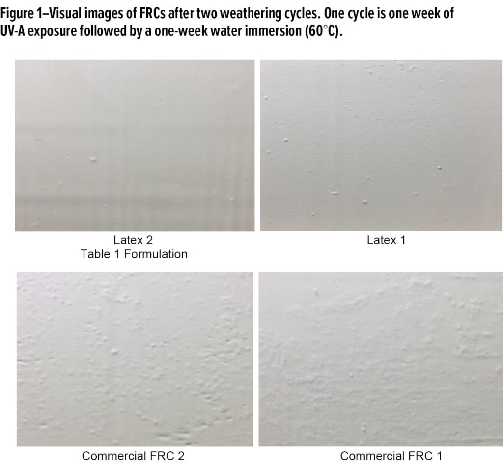
Figure 1 shows photographs of the four acrylic FRCs applied to galvanized steel after two weathering cycles where each cycle was one week of exposure to UV-A radiation followed by one week of immersion in 60 oC DI water. In general, the common visual defects, if they occurred, were small blisters and surface pitting. In addition, the two commercial FRCs yellowed slightly after UV-A exposure and tended to show more blister formation compared to Latex 1 and 2. No significant adhesion loss was observed for any of the coatings.
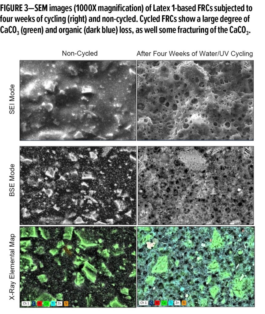
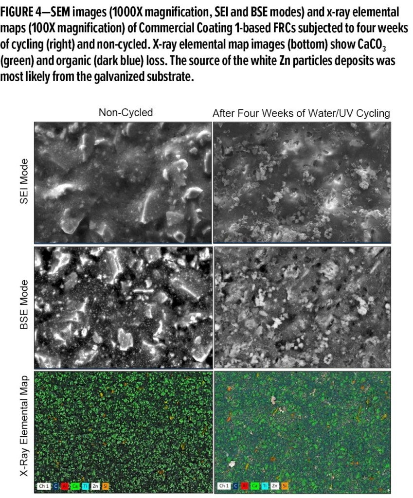
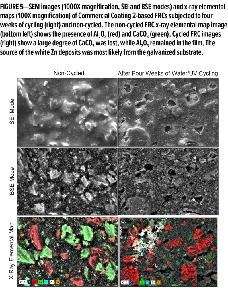
Figures 2–5 show SEM and EDS images comparing FRCs after two weathering cycles (left images) and coatings simply stored at 25 oC with 50% RH. All FRCs contained TiO2 and used a large (≈ 10 mm) particle size CaCO3 as a filler. In addition to CaCO3, Commercial Coating 2 also contained alumina (Al2O3). The alumina is most likely added as alumina trihydrate commonly used to impart flame retardancy.
A comparison of SEM images before and after weathering shows varying degrees of surface morphology change for all FRCs. Examination of weathered film images shows the common defect was void or crack formation at the binder/CaCO3 interface along with CaCO3 particle fracturing and removal from the film surface. In some cases, surface cracking also developed between filler particles or between cavities left from filler removal. The x-ray elemental images show not only filler removal but also some carbon loss suggesting polymer removal.
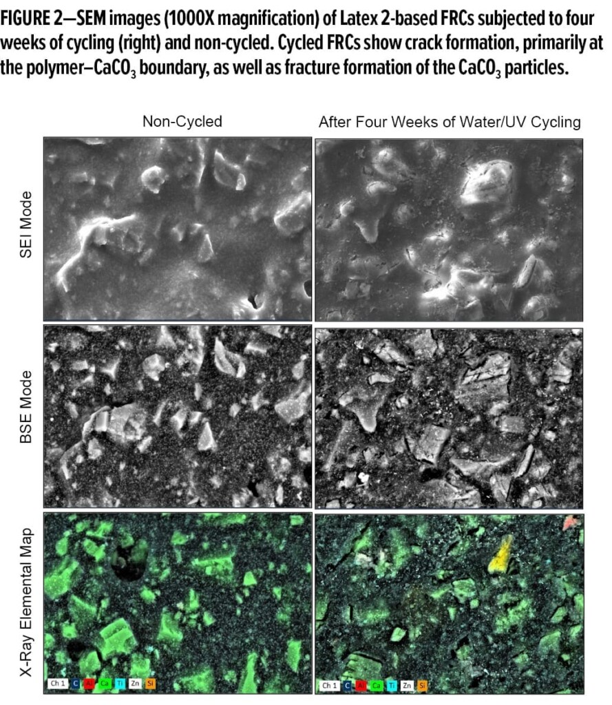
The changes to the surface morphology of FRCs based on Latex 1 and Latex 2 after weathering show significant differences, Figure 2 and Figure 3, respectively. The Latex 2-based coating shows (Figure 2, top left) crack formation near the CaCO3 boundaries. These cracks are clearly more visible in the x-ray elemental images (Figure 2, bottom right) where fracturing of the CaCO3 particles is also evident. In addition, small cracks formed in regions between CaCO3 particles. The x-ray image (Figure 2, bottom left) shows removal of only a small amount of CaCO3 from the surface. Figure 3 shows significant changes to the surface of the FRC based on Latex 1 after weathering. The SEM images show significant removal of surface CaCO3 along with dense void formation. In addition to carbonate removal, the x-ray image shows significant removal of organic phase (carbon signal).
The commercial FRCs appear to have degraded in a similar manner as the Latex 2-based coating although to a slightly greater extent with more loss of surface CaCO3. Commercial FRC 1 (Figure 4) had more surface void formation and slight surface cracking compared to Latex 2, but to a much lesser extent than Commercial FRC 2. Commercial FRC 2 (Figure 5) contained the two fillers CaCO3 and Al2O3, but only CaCO3 fracturing and removal occurred after weathering. The Al2O3 particles showed no apparent fracturing and remained in the film with no void formation at the filler-polymer boundary.
Film cross-section imaging, Figure 6 and Figure 7, show that morphology changes in the coatings was confined close to the film surface to a depth of about 10 mm to 20 mm or about a CaCO3 particle diameter. This is more clearly seen in Figure 6 for Latex 1. The roughed appearance of the fractured CaCO3 particles in the bulk of the film was most likely caused by the microtoming process.
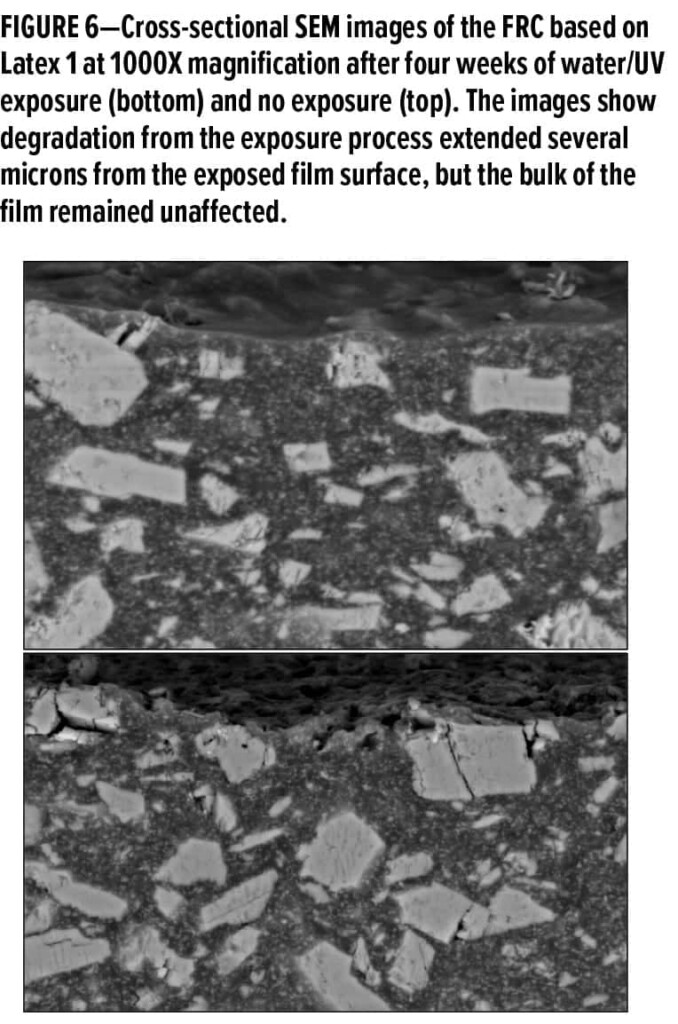
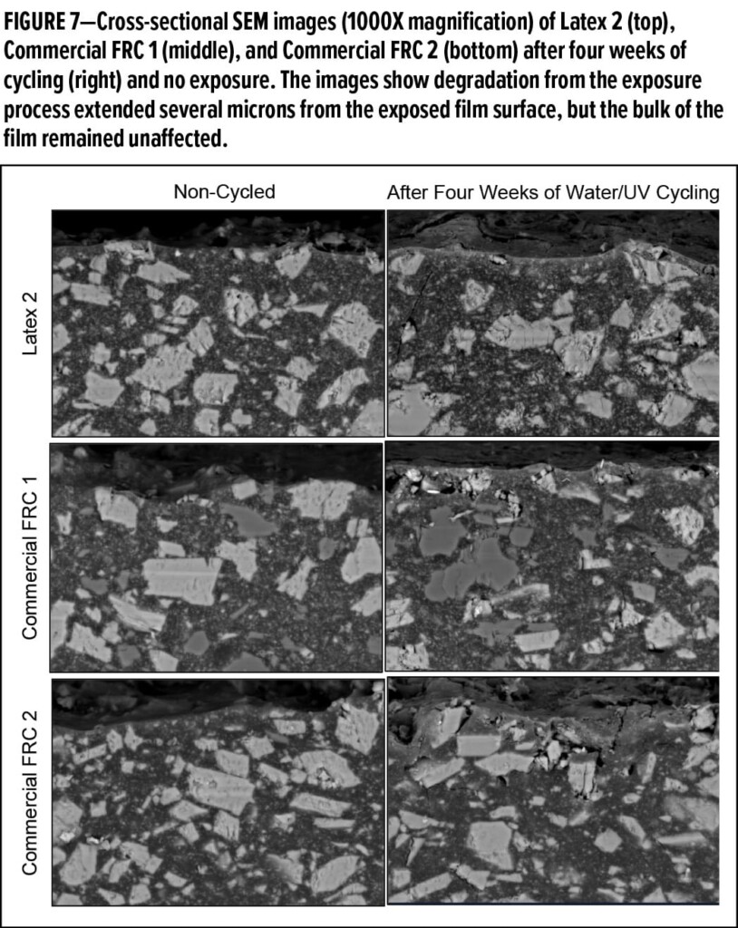
Figure 8 shows Latex 2-based FRCs formulated with the fillers Minex3 and Imsil and the two dispersants Dispex CX-4231 and Dispex AA-4144. These coatings exhibited significant crack formation that extended many filler particle diameters across the film and along the filler-polymer boundaries. Unlike CaCO3, Minex and Imsil particles remained intact within the film showing no signs of fracturing. The choice of dispersant in Minex-containing coatings had a slight influence on cracking where the degree of cracking was somewhat less when using Dispex CX-4231.
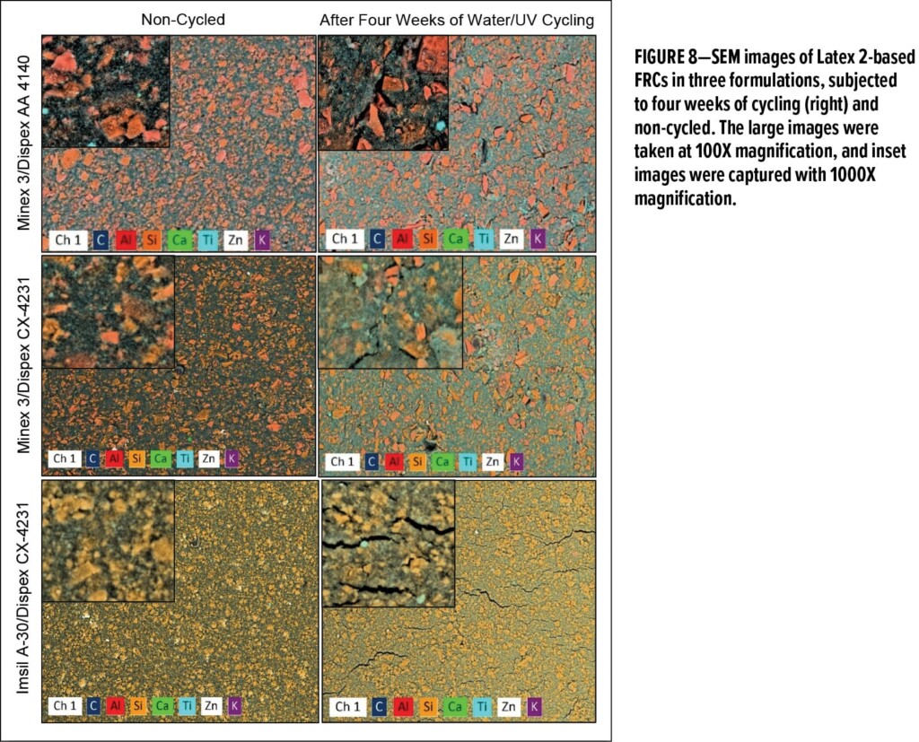
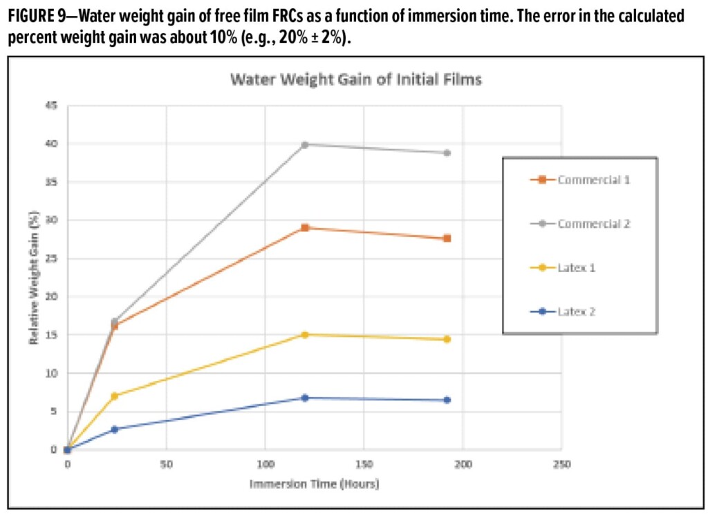
Figure 9 shows water weight gain vs immersion time for free-film FRCs. The data show different degrees of water weight gain varying from about 6% to about 40% once equilibrium is reached at about 120 h immersion time. The measurement error was about 10% of the calculated percent weight gain. The coatings-based Latex 2 had a relative weight gain that was a little less than half that of Latex 1.
Discussion
The simple accelerated cyclic testing protocol developed here for gauging water ponding resistance showed differentiation for macroscopic and microscopic surface morphology changes among FRC formulations. The results suggest an approximate ranking from best to poorest performance based on the microscopic observations:
Latex 2 ≥ Commercial FRC 1 > Commercial FRC 2 > Latex 1.
The differentiated macroscopic defects (blistering) suggests the ranking:
Latex 1 > Latex 2 > Commercial FRC 1 > Commercial FRC 2.
It is, of course, important to keep both macroscopic and microscopic film defects in mind when rating overall performance because both probe different, although related, aspects of failure; microscopic surface degradation appears more specific to the intrinsic coating composition and macroscopic defects are specific to both coating composition and the substrate (e.g., adhesion to galvanized steel in this case).
It is generally understood that accelerated lab tests for exterior durability can, at best, provide a relative ranking rather than absolute performance over time. One must also bear in mind the above rankings may only hold for a specific exterior exposure time interval and that differences may vanish upon further weathering. That is, it is not known whether the testing time (two cycles) is providing a degradation rate that remains constant. Further, it would be instructive to compare the current test to other established cyclic testing of coatings such as ASTM D4799. In any case, the relative performance suggested by the current test needs verification through real-world exterior water ponding exposures.
The SEM images of weathered acrylic FRCs containing CaCO3 suggests film degradation partly occurs by CaCO3 particle degradation (fracturing and possibly dissolving) followed by detachment from the binder phase and subsequent loss from the film. The SEM images also show, in some cases, cracks formed between film voids left from CaCO3. The deterioration of CaCO3 may be caused by exposure to water in combination with formulation ingredients (dispersants, polymeric acid groups, etc.) and where the local pH drops. This degradation mechanism is similar the commonly observed “chalking” in other CaCO3 continuing coatings exposed to exterior environments.
Commercial FRC 2 (Figure 5) was formulated with both CaCO3 and Al2O3 where the weathered images clearly show that while CaCO3 deteriorates and is lost from the coating, the Al2O3 particles remain intact and anchored within the film. This suggests Al2O3 is more inert to the surrounding environment than CaCO3. It may also be possible that Al2O3 particles are better anchored into the film though interaction with functional groups (e.g., acids) on the latex binder. This would be analogous to the integration of other metal oxides (e.g., TiO2) with latex binders that promote adhesion and pigment–binder composite formation for improved coating opacity.
Because changes in film morphology from filler and binder loss appeared only in the top-most regions of the films after weathering, the results suggest an FRC degradation mechanism, which initiates at the (weathered) exposed surface and proceeds by continual loss of mass (filler, binder, etc.). If this mechanism accounts for most of the degradation process, then eventually, assuming no other catastrophic failure occurs (e.g., adhesion loss, blister formation, biological attack, etc.), continual mass loss will cause film-thinning to a point where mechanical stresses (e.g., substrate movement, water swelling, etc.) causes film cracking that extends to the roofing substrate. However, significant mass loss may need not take place for failure as continual crack formation and crack coalescence alone could severely degrade performance.
Water swelling of free films appears to play a role in coating defect formation. The relative amounts of water adsorption (Figure 9) appear to roughly correlate with visual film appearance (Figure 2) but not as well as with the extent of micro surface degradation. The commercial FRCs had the highest levels of water uptake and the most blister formation compared to the other coatings. This correlation is probably only a first approximation because of the cyclic nature of the test where water-soluble and dispersible formulation ingredients are extracted from the films, potentially affecting subsequent water uptake levels, mechanical properties, etc.
The significant difference in surface morphology after weathering between Latex 1 and Latex 2 is explained, partly, through compositional differences. Latex 2 is more hydrophobic and had lower acid relative to Latex 1 and would be expected to adsorb less water. This appears to be the case from the water swelling results. In addition, post film formation crosslinking is expected to provide some resistance to water swelling and some measure of dimensional recovery once water has evaporated. In the case of Latex 1, more volume swelling along with more unrecoverable deformation may have allowed for more easy removal of CaCO3, giving a more disrupted surface upon drying.
The SEMs in Figure 8 show the choice of filler significantly impacted surface morphology changes after weathering and the degradation mechanism for coatings based on Latex 2. Carbonate-containing coatings had cracking largely confined around CaCO3 particles while formulations using Minex 3 or silica (equal volume) show significant crack propagation extending tens of microns. Also, in contrast to CaCO3, Minex 3 and the silica particles appear to remain intact and anchored in the film.
Part of the failure mode differences are explained by the formulation PVC relative to the critical PVC1, L:
L = PVC/CPVC where CPVC is the critical PVC, which depends on the pigment/filler type and the latex binder.
It is well known that many coating properties rapidly change as the PVC approaches the CPVC.1 In this case, the likelihood of crack formation due to internal film stress caused by water adsorption/desorption and UV exposure is expected to increase as L approaches 1.
The CPVC can be estimated by:
CPVC = 1/(1+r*AO/93.5)
Where r is the filler density and AO the filler oil adsorption. The AO values for CaCO3, Minex 3, and Imsil A30 are approximately 10, 28, and 25, respectively, and the formulation PVC was 43. All fillers have a density of about 2.65 g/cc. These quantities give estimated L values of 0.55, 0.78, and 0.74 for CaCO3, Minex 3, and Imsil A30, respectively. These estimates show the coating based on Minex and Imsil formulations are much closer to the CPVC than CaCO3, suggesting an increased likelihood for cracking. Given that Minex and Imsil are known to be more durable in the exterior environment than CaCO3, a simple solution to reduce or eliminate cracking using these fillers is to reduce the formulation PVC.
Conclusions
- The suggested laboratory test has the potential to distinguish (rank) water ponding resistance among FRCs in a short time (≈ one month) frame and potentially aid in the development of new, more durable FRC formulations.
- Assuming the absence of catastrophic (macroscopic) failure such as widespread adhesion loss and blister formation, degradation by exposure to ponded water is through gradual mass loss at the exposed surface.
- Coating mass loss is affected by the type of filler, polymer composition, and interface between filler and polymer.
- Low water adsorption of free films is a necessary but not a sufficient FRC characteristic for good water ponding resistance.
- Potential routes towards better water ponding resistance of acrylic-based FRCs are suggested by using low levels of inert fillers along with latex binders having low acid content, toughness, and dimensional recovery.
Reference
- Patton, T.C.; Paint Flow and Pigment Dispersion: A rheological Approach to Coatings and Ink Technology, 2nd Edition, 1979, A Wiley-Interscience Publication.
CoatingsTech | Vol. 17, No. 6 | June 2020