
By Lance C. Kelly, Defence Science & Technology Group
Infrared-(IR) based weaponry and surveillance systems utilizing the short-wave, mid-wave, and long-wave IR emissions produced by ambient to high-temperature surfaces are an existing and continually evolving threat to military platforms. The survivability and sustainability of aircraft, helicopters, ships, and land vehicles depend on adequate protection against these threats. IR emissions from an object can be reduced by the use of an easily applied, low-weight, and passive low-emissivity coating for a relatively low cost. Several low-emissivity coatings with visual camouflage colors used by the Australian Defence Force (ADF) have been formulated that have lower emissivity in the critical IR transmission windows in the thermal IR when compared with conventional military coatings. A low-emissivity IR coating based on the camouflage color Aerospace Material Specification Standard 595 36375, a color that is employed by the Royal Australian Air Force on a number of ADF platforms, was formulated and tested against two topcoat specifications, MIL-PRF-85285E and DEF(AUST) 9001A.
Introduction
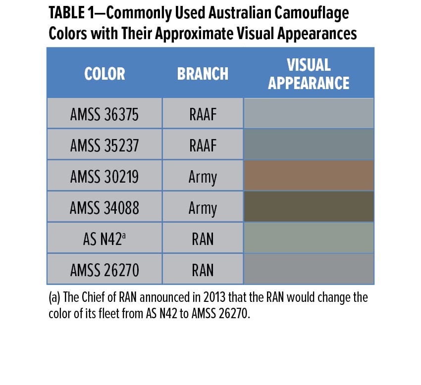
Camouflage is the method of using a natural or artificial material on personnel, platforms, or tactical positions with the aim of confusing, misleading, or evading an enemy.1 It is an essential attribute for any modern military platform, which, together with operational tactics, greatly improves the survivability and operational capability of the platform and personnel involved. Selected visual camouflage colors from the Aerospace Material Specification Standard 595A series (AMSS),2 used for Royal Australian Air Force (RAAF) aircraft and Australian Army (Army) vehicles, or the Australian Standard (AS)3 series, some of which are used for Royal Australian Navy (RAN) vessels, are listed in Table 1.
Visual camouflage coatings, apart from providing protection from corrosion and weathering, can also be formulated to provide camouflage in other parts of the electromagnetic spectrum (EMS) outside the range detectable by the human eye (having an operating range of 0.38–0.78 mm), such as the infrared (IR). Since the 1990s, research at the Defence Science and Technology (DST) Group on the IR properties of military topcoats has focused on the near IR (NIR) for purposes of reflecting incoming solar radiation to reduce heating of military equipment4 and active night vision goggle camouflage.5 More recently, work has been completed in formulating coatings that assist with camouflage in other parts
of the IR spectrum.
This article presents results of the work undertaken to test the performance of ambient cure low-emissivity (LE) versions of the camouflage colors listed in Table 1 designed for operational performance for temperatures ≤ 250°C. LE coatings for high-temperature (> 250°C) applications rely on a different technology that will not be covered in this article. One color, AMSS 36375, was selected due to its wide operational use in the RAAF, a branch of the Australian Defense Force (ADF). The color was formulated as an LE coating and tested against both the MIL-PRF-85285E and the DEF(AUST) 9001A specifications.
Infrared Theory
Thermal Infrared
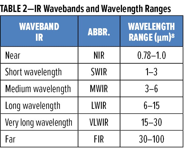
Many definitions exist for the boundaries within the IR component of the EMS.6-8 For this article, these wavebands will be based on semiconductor material responses, as listed in Table 2.
At longer wavelengths beyond the NIR, self-emissions from objects (referred to as “thermal” radiation) become dominant. Due to the quantum nature of our universe, all objects above absolute zero emit radiation.
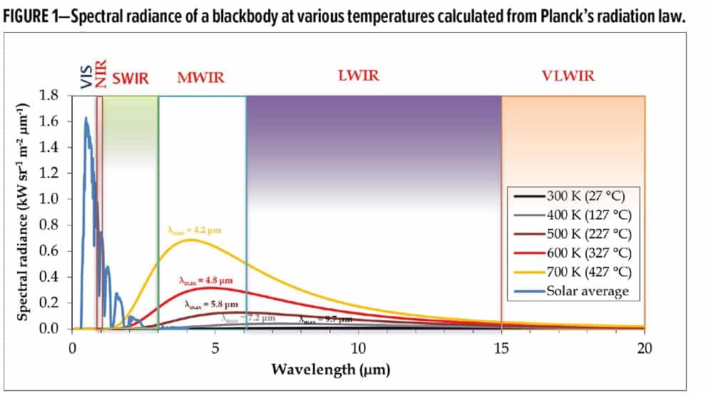
For a blackbody (a theoretical object that absorbs all the energy of all the wavelengths of the incident radiation9) at thermal equilibrium, the spectral radiance of the thermal radiation emitted from the blackbody can be calculated and plotted (Figure 1) using Planck’s radiation law10 as given by equation (1):
(1)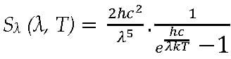
where l is the wavelength (m), c is the speed of light (2.998 × 10⁸ m s-1), k is the Boltzmann constant (1.38 × 10⁻²³ J K-1), S is the spectral radiance (W sr-1 m-2 mm-1), h is Planck’s constant (6.63 × 10⁻³⁴ J s), and T is the absolute temperature in Kelvin.
The wavelength of the peak radiation can be calculated using Wien’s displacement law,11 given by equation (2):
(2)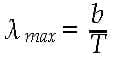
where b is Wien’s displacement constant (2.898 × 10⁻³ m K).
Planck’s radiation law demonstrates that the effect of increasing temperature on spectral radiance is nonlinear and that emittance increases rapidly with temperature. For simulated temperatures where the blackbody temperature increases from 300 to 700 K, the peak thermal emission wavelength shifts from the LWIR into the MWIR waveband and the spectral radiance increases. Thermal emissions of an object in these wavebands are referred to as thermal infrared (TIR) emissions. In these wavebands, the average solar thermal output from the Sun12 (itself a blackbody at 5780K13) is negligible, providing a method to detect objects free from solar interference. As only minor amounts of TIR radiation are emitted in the VLWIR waveband, this contribution to the total TIR will be ignored in this article as it has no military value in this technology field.
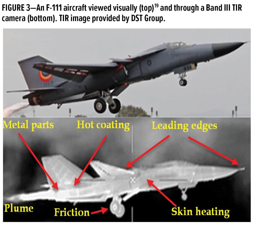
Sources of TIR self-emissions from military platforms include hot exhaust plumes, hot end components near plumes, aerodynamic heating of leading edges, and heating of the skin.14 Minor levels of TIR radiation are also generated by reflection of radiation from warm terrestrial sources. The type of TIR self-emissions generated by military equipment is dependent upon its design and purpose, e.g., an aircraft might display elevated TIR emissions due to aerodynamic heating of the airframe or from operation of its afterburner; a warship might exhibit strong TIR emissions from its heated funnel or exhaust plumes.
Because an object emits TIR radiation, it produces a TIR signature allowing its detection by passive TIR sensors that acquire this radiation. The advantages of using TIR imaging technology is that it is useful for in-field detection (IR waves do not refract over the horizon), identification, and tracking. TIR radiation is also less scattered by fog, smoke, or dust particles as compared with visible wavelengths. As TIR sensors are passive systems, the power requirements and the probability of detection of a passive TIR detector are relatively low when compared with active source systems, such as LIDAR and RADAR.15 Thus, TIR targeting and tracking devices are difficult to detect and eliminate.
Molecules of water and carbon dioxide in the Earth’s atmosphere significantly attenuate IR radiation within the TIR wavebands of the EMS. Carbon dioxide absorbs radiation at wavelengths of 2.7, 4.3, and 15 mm while water vapor absorbs radiation at wavelengths of 1–2 and 5–8 mm.16 Attenuation effects can be observed when the atmospheric absorption17 is overlayed on the spectral radiance plots (Figure 2).
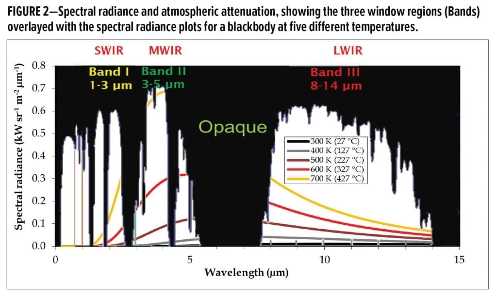
Many of the TIR self-emissions are attenuated, but three main transmission windows exist at 1–3, 3–5, and 8–14 mm (called Bands I, II, and III, respectively). TIR radiation within the VLWIR and FIR wavebands are completely attenuated. Transmission windows allow emitted TIR radiation to propagate through the atmosphere and be detected by TIR sensors attached to trackers and guided missiles. The transmission windows (Bands), their wavelength ranges, typical sensor materials used to detect these emissions, and the common sources of these emissions are shown in Table 3.
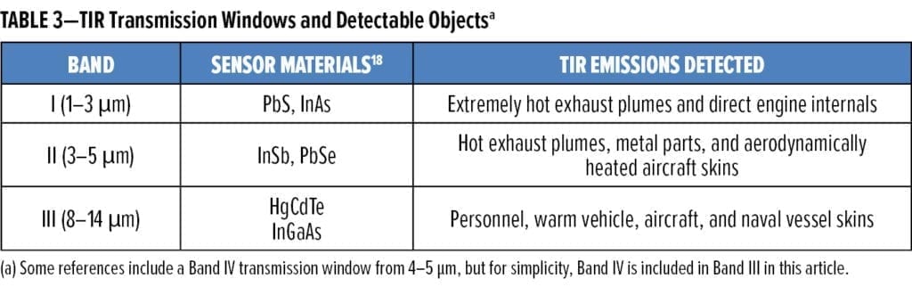
Band I emissions, derived from extremely hot engine parts and from plumes of an aircraft, ship, or land vehicle can only be observed from discrete aspect angles. For example, Band I emissions from an aircraft are usually emitted from the rear sector of an aircraft; therefore, Band I-guided missiles detect, then approach an aircraft from behind. Band II sensors are a higher-priority threat for aircraft18 due to strong plume emissions and aircraft skin emissions from leading edges in that band. Plume and aircraft skin emissions allow an all-aspect profile in this transmission band; therefore, the aircraft can be tracked and targeted as it moves toward, or tangentially, to a Band II detector or guided missile. For “cooler” objects, such as personnel and the skin of aircraft, land, and naval vessels, detection by Band III detectors is of concern, as Band III emissions also allow an all-aspect profile. Aircraft are the most exposed, as they are usually imaged against a cold sky, whereas a land vehicle or naval vessel may have outer skin temperatures closer to that of the surroundings.
The ease with which objects can be imaged by a TIR sensor can be demonstrated with an F-111 aircraft as viewed with a Band III thermal camera (Figure 3). Intense TIR emissions are observed from extremely hot exhaust plumes and hot metal parts on the nacelles. The exhaust plumes, being composed of gaseous combustion products, are dominated by the carbon dioxide and water vapor emission bands. While intense at the source, they are absorbed by the atmosphere and are, therefore, more rapidly attenuated with distance, unlike emissions from the hot surfaces near the aircraft nacelles or the skin of the aircraft, which are heated by aerodynamic friction.
Examples of TIR-guided missiles include the AIM-9 Sidewinder and FIM 92 Stinger from the United States and the 9K333 Verba from Russia.20-22 The use of TIR-guided missiles has influenced battle tactics and outcomes throughout the latter half of the 20th Century.23,24
There are several countermeasures that may be used against TIR-guided trackers and missiles. Engineering modifications, such as shrouding hot components and plumes, have been employed.25 Active cooling, the process of reducing the engine and plume temperatures to shift the wavelength of maximum emittance to those attenuated by water and carbon dioxide, is achieved by using a turbofan that can pass incoming cool air over the engine components and into the plume, or by using cooler recirculated on-board fuel as a heat sink.26,27 These methods reduce Band I emissions, but emissions from Bands II and III remain. In many cases, these modifications add weight, reduce operability, are costly, and are difficult to upgrade. Chemical-based pyrotechnic flares are used (Figure 4) to produce a spectral emittance profile similar to that of the hot parts of military equipment to confuse and seduce a thermal-seeking missile. However, smart missile imagers can differentiate between flares and aircraft.29 IR-jamming utilizes lasers to blind TIR detectors and break the target lock.30 Even if dazzled, advanced sensors can still detect the target.31
Low-Emissivity Coatings
If the temperature of an object cannot be lowered, a simple, low-cost, passive method of reducing the TIR signature of an aircraft is to apply an LE coating over the hot areas to suppress TIR emissions. If Planck’s radiation law is integrated over all wavelengths, the total radiant exitance by a blackbody per-unit time and per-unit area is given by the Stefan-Boltzmann law32 [equation (3)]:
(3)![]()
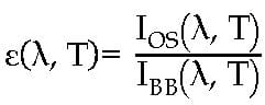
where I is the radiant exitance (W m-2), s is the Stefan-Boltzmann constant (5.67 × 10⁻⁸ J s-1 m-2 K-4), and e is the emissivity of the material. In this equation, s is fixed and T4 is the main contributor to radiant exitance. Emissivity, a dimensionless number ranging from one to zero, is defined as the ratio of the radiant exitance of an object’s surface (OS) to the radiant exitance of a blackbody (BB) with an emissivity of one at the same wavelength and temperature at thermal equilibrium, as shown in equation (4).33 Emissivity is the only contributor to the radiant exitance that can be altered.
(4)
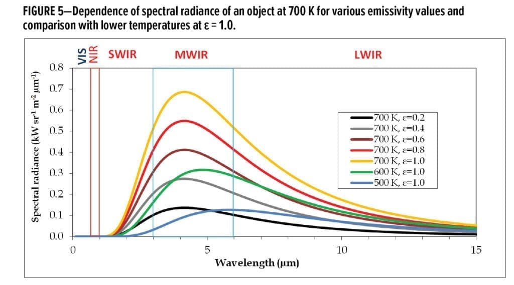
Lowering the emissivity of a material reduces the apparent temperature of an object by reducing the quantity of radiation emitted; however, it does not change the peak wavelength of the thermal emission or its true physical temperature. The spectral radiance in the TIR wavebands of an object at 700 K, for example, is shown to depend strongly on the value of the surface emissivity (Figure 5). By lowering the emissivity, the spectral radiance curves can be altered to appear similar to the spectral radiance of cooler objects; for example, objects at 600 and 500 K.
Conventional coatings currently used on military equipment are formulated with materials that display an emissivity approximating 0.95 (approaching that of a BB)34 and, therefore, emit a near theoretical TIR maximum. It is possible to formulate LE coatings that have visible camouflage properties similar to conventional coatings while simultaneously suppressing thermal emissions. This allows reduction in the detection range (determined by the inverse square law) and better camouflage of the platform in its operating environment when viewed in the TIR.
LE materials include conductive materials (those that contain mobile electrons), such as gold, chromium, zinc, copper, silver, and aluminum,35 and semiconductors (with low-valence band energies), such as silicon or lead compounds. When fabricated as pigments, the LE materials can be dispersed into binders to produce coatings with a range of emissivity properties. When tinted with conventional pigments, the desired visual camouflage color can be achieved. The physical advantages of using LE coatings are principally the reduction of thermal emissions in Bands I to III from operational platforms. It must be noted that the LE coating would only be applied to the hotspots of a military platform. Due to the law of energy conservation, it is desired that TIR radiation not emitted from the surface be redirected to noncritical directions that have a lower probability of detection. This is to prevent a thermal insulation effect that would raise the temperature of the entire platform if coated in its entirety with LE material.
Strategic advantages in formulating LE coatings in-house include provision and control of sovereign technological capability in thermal suppression, which enables rapid LE formulation changes in required colors and emissivity levels as dictated by operating environments and mission needs.
Defence Specifications
Commercially available LE coatings are generally not formulated to colors used by the RAAF, RAN, or Army, and none have been fully qualified to current ADF specifications. The main topcoat specifications used by the ADF are listed in Table 4.
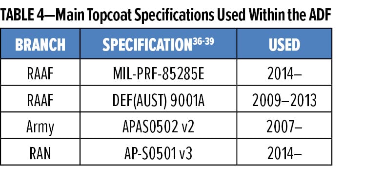
The current specification used for qualification of most RAAF topcoats is U.S. Military Specification MIL-PRF-85285E, “85285E”, released in 2012. Prior to this, coating specification DEF(AUST) 9001A, “9001A”, released in 2009 by the Commonwealth of Australia, governed the use of both primer (qualified to MIL-PRF-23377)40 and topcoat as a total coating system for operational RAAF aircraft. Specification 9001A contained many similar tests to MIL-PRF-85285D41 but incorporated more demanding accelerated UVA weathering and corrosion requirements suited for Australian conditions. Also, 9001A removed restrictions on volatile organic compounds (VOCs) and relaxed the requirement for coating flexibility. It was subsequently withdrawn from use in September 2013 due to the inclusion of a Type IV coating category into the 85285E specification, i.e., aircraft application with extended weatherability. Prior to the release of 85285E, many military coatings developed in Australia, including the LE coatings, were formulated to conform to the requirements of 9001A.
Existing ADF topcoat specifications are used as a requirement for expected performance of coatings used for Defence applications. The formulated LE coatings have their own unique properties, such as TIR emission reduction and, therefore, it may be difficult for LE coatings to pass all requirements. This will not preclude the use of LE coatings on ADF equipment due to the unique properties these coatings provide. The information gathered by testing LE coatings against the requirements of the specifications is important if critical coating properties, such as adhesion, are to be deemed acceptable for the intended application. Due to the wide operational use of the AMSS 36375 color by the RAAF, an LE variant was formulated to this color and tested against the 9001A and 85285E aircraft topcoat specifications.
Preliminary work to obtain an emissivity of less than 0.5 in Bands I, II, and III while maintaining general coating integrity had been previously conducted. However, tinting of these prototype coatings to camouflage colors was not achieved, and testing conformance against a coating specification was not attempted.
Experimental
Substrate Preparation
Plain aluminum panels with a thickness of 1.2 mm were cleaned by scrubbing with a 3M Scotch-Brite 7447+ pad soaked in a 33% aqueous solution of Bonderite C-IC 624 Acid Cleaner (Henkel), then rinsed with tap water. The process was repeated until a water break-free surface was obtained. For aircraft-related coating tests, panels were pretreated by immersion in a chromate solution at 23 ± 2°C for 35 s. The chromate solution was prepared by dissolving 8.0 g of Bonderite M-CR 1200S Aero in one liter of water, adjusted to a pH less than 2.0 with aqueous nitric acid (if required), and used within 24 h. Following removal from the chromate solution, the test panels were rinsed with tap water and allowed to dry for 24 h at ambient temperature before application of primer. For filiform and salt fog corrosion testing, coupons composed of aluminum alloy clad 2024-T3 with a thickness of 1.2 mm were employed and prepared in the same manner as the plain aluminum panels. For impact and aged impact testing, aluminum alloy clad 2024-0 coupons with a thickness of 0.5 mm were employed as the substrate.
For cold flexibility tests, 0.3 mm tinplate was employed as the substrate. The tinplate was prepared by abrading with P360-grit emery paper and then cleaned by wiping with a cloth soaked with methyl ethyl ketone (MEK).
Commercial Coatings
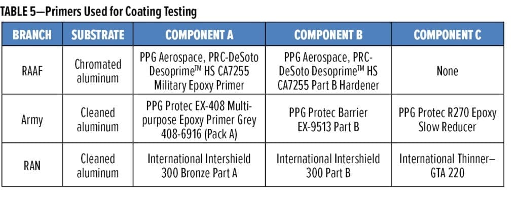
For all the panels tested, the primers used are shown in Table 5, where Component A (base component) and Component B (curing agent) were mixed together at the suppliers’ recommended volume ratios. Component C was then added to provide a viscosity suitable for spray application (20–30 s through a Ford 4 flow cup). The liquid coating was allowed to stand at 23±2ºC for 20 min before being transferred to the spray gun. A commercial polyurethane AMSS 36375 topcoat conforming to specification MIL-PRF-85285E, Type I, Class H was applied over the CA7255 primer and used as a control for comparison with the experimental LE AMSS 36375 coating.
LE Coatings
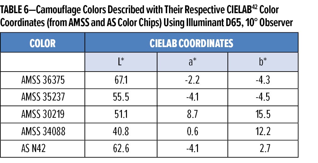
LE coatings were manufactured at the DST Group laboratory by blending hydroxyl functional polyester resins, additives, and organic solvents to form a homogenous mixture. The TIR-suppressing pigments were dispersed into this mixture using a high-speed disperser at a speed not greater than 500 rpm. The visual camouflage colors listed in Table 6 were then achieved by stirring in solid-color pigment concentrates formulated at DST Group. Addition of aliphatic isocyanate hardeners then completed the formulation.
Coating Application
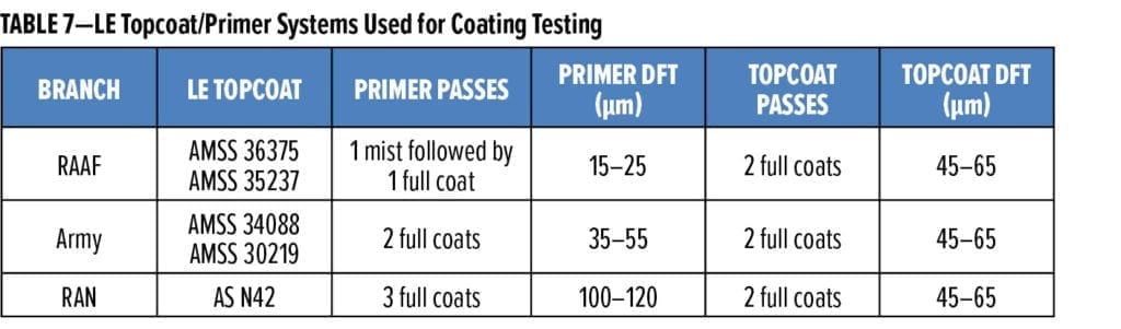
Spray application was performed with a gravity-fed Anest Iwata W-400-132G LV-2 spray gun with a pressure of 241 kPa (35 psi), maximum fan (aperture), and full fluid flow. All coatings were filtered through a 190 mm fine nylon filter cone before application. Application conditions were 23 ± 2°C and 30–70% relative humidity (RH). Wet and mist coats were applied moving the spray gun horizontally at a speed of 0.2–0.4 m s-1 at an application distance of 0.15 m from the panel with sufficient overlap of passes to obtain the required dry film thickness (DFT). Solvent flash-off from each coat was required to be complete before commencing the next pass. Topcoats were applied 4–24 h after application of primer. The topcoat colors and coating DFTs are listed in Table 7.
Coating Assessment
Coatings were allowed to cure for one week under ambient conditions for gloss and color measurements or two weeks under ambient conditions for all other coating tests. American Standard Test Methods (ASTM), ISO Standards, and the Australian Standards 1580 series quoted in the testing phase can be found at the ASTM International website and Standards Australia.43,44
Color Measurement
CIELAB (CIE 1976 L*a*b* color space)44 color measurements were conducted using a Konica Minolta CM-2500d spectrophotometer. Calibration was completed with a Spectralon white tile and a Konica Minolta CM-A32 Zero Calibration Box. Color measurement conditions were observer 10° and illuminant D65. An average of three scans was taken. Specular component-included (SCI) values are reported. Total color difference (DE*ab) was calculated using equation (5):
(5)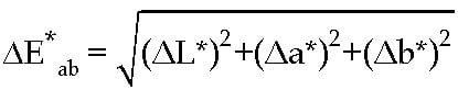
where DL* is the lightness difference on the L* axis, Da* is the red-green color difference on the a* axis, and Db* is the yellow-blue color difference on the b* axis.
AMSS series color standards45 were stored in a dark refrigerator when not in use to minimize color drift between uses. Standards were allowed to equilibrate to room temperature for 30 min before being used for color measurements.
Gloss Measurements
Specular gloss measurements of coatings were made using an Elcometer 402 NOVO-GLOSS Statistical Glossmeter. Calibration was conducted using a highly polished reference black glass standard with a defined refractive index, having a specular reflection of 100 gloss units (GU) at the specified angle. The lower end point was established at 0 GU using a near-perfect black matte surface. Gloss measurements were recorded simultaneously at three specular directions to the normal (20°, 60°, and 85°). Three measurements were made at different points on the coating, and the values reported for each angle were the average of these.
Accelerated Weathering
Accelerated weathering of coatings was undertaken using a Q-Lab Products Q-Sun Xe-1 Xenon test chamber in combination with Q-Labs 1800 W, 800 V Xenon Lamp, and a Q-Sun Daylight Q filter. The conditions used (following ASTM G155)46 were a constant spectral irradiance of 0.70 W/m2/nm at 340 nm and a black tile temperature of 63°C for 102 min alternating with irradiance in combination with water spray for 18 min (air temperature not controlled).
Coatings removed from the Q-Sun test chamber were then allowed to dry overnight at ambient temperature to remove, by evaporation, any sprayed water from the coating before measurements of color, gloss, and weight were conducted.
Exterior Exposure
Test panels were placed on an exposure rack at a seasonally adjusted angle (November–April 20°N, May–July 55°N, August–October 37.5°N) at Monegeetta, Victoria, Australia (latitude -37.93°S and longitude 144.77°E). Coatings placed for exterior exposure were measured for changes in color, gloss, chalking, and weight biannually. After each exposure period, the weight of the coating was measured, and the entire coating was rinsed under a gentle stream of water to remove loose dirt. The right side of the coated panel was gently wiped up and down 10 times with a water-soaked cotton wool swab. The left side was kept unwiped to estimate dirt pick-up. The coupon was then allowed to dry overnight at ambient temperature. Color and gloss changes on the wiped and unwiped sides of the coating were measured at the same three distinct locations, and the panel was re-weighed. The degree of chalking was rated by the tape test conducted on the wiped and unwiped sides using the method of AS/NZS 1580.481.1.11:199847 with 3M Scotch 600 Transparent Tape. Exposure panel weights were recorded using a Sartorius 1702 electronic balance.
Infrared Reflectivity Spectrum Analysis
Emissivity measurements of coatings were conducted using a Nicolet 5700 Fourier transform infrared spectrophotometer with a 75 mm diameter OpTec gold-coated integrating sphere, Model A562, over the 2–25 mm wavelength range. The total spectral reflectivity, r, (both specular and diffuse components) was measured by placing a gold-coated port plug (reference material) into the bottom sampling port and the sample on the top port. The beam was directed onto the diffuse gold reference to record a reference measurement. The beam steering mirror was then rotated to direct the beam onto the sample to collect the TIR spectrum. The following parameters were used to collect the TIR spectra: resolution, 8 cm-1; number of scans coaveraged, 500; scan velocity, 0.3165 cm s-1; acquisition mode, double sides, forwardbackward, apodization, Happ-Genzel; phase correlation mode, Mertz, zero; filling: none. A deuterated lanthanum alpha-alanine-doped triglycine sulphate detector was used for the measurement and the diffuse gold plug (Infragold) as the reference material. The sampling area was approximately 10 mm in diameter.
Using Kirchhoff’s Law and Helmholtz’s reciprocity theorem,48 the emissivity (e) for an opaque surface was calculated using equation (6).
(6)![]()
Dry Film Thickness
Dry film thickness (DFT) reported for primers and topcoats was obtained with an Elcometer 355 Coating Thickness Gauge.
Thermal Degradation
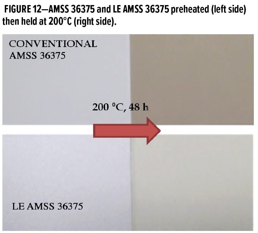
Test panels were primed and topcoated with the conventional coating or the LE variant and cured for two weeks under ambient conditions. Coatings were placed in an oven set to 200°C and held at this temperature for 48 h. Color measurements were made on both control and thermally treated samples, and the color differences were calculated using equation (5).
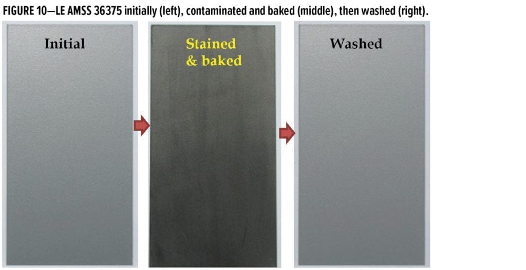
Cleaning Efficiency
Cleaning efficiency (CE) for both the LE and conventional coatings was undertaken using the method described in 85285E. Artificial soil was produced by dispersing 50 g of Vulcan XC72 carbon black pigment (Cabot Corporation) in 500 g of Royco 782 hydraulic fluid (conforming to MIL-PRF-83283)49 with a high-speed disperser at 2500 rpm for 15 min. The artificial soil was applied by brush onto clean coatings where the value of L* under SCI conditions, as previously described, had been measured (value A). Excess soil was then removed with a paper towel pressed down by a 2.5 kg rubber roller. The soiled surface was subsequently brushed to provide an even dark surface. Coatings were then baked at 105 ± 2°C for one hour, cooled, and the L* values again measured (value B). Coatings were then gently washed twice with paper towels dipped in a 20% w/w aqueous mixture of Calla 855 (an alkaline cleaning solution conforming to MIL-PRF-8557050). The coatings were then rinsed with tap water, dried, and L* was measured again (value C). Cleaning efficiency was calculated using equation (7):
(7)![]()
Thermal Measurements
Thermal images of low-emissivity and conventional coatings were compared in the wavelength range of 7–13 mm using an FLIR® Systems ThermaCAM P60 camera. Coated panels were placed on a preheated hotplate for 15 min to obtain thermal equilibrium. False color images were displayed with thermal ranges, and temperature was automatically generated by the ThermaCAM. ThermaCAM settings were e = 1.00, observation distance 1.0 m, humidity 50%, and relative temperature 24°C.
Results
Initial Work
Before commencing testing against the aircraft coating specifications, initial work involving accelerated weathering on the LE coatings was conducted to determine if sufficient durability had been achieved. Durability was assessed by examination of color and gloss changes of the LE variants exposed to UVA under accelerated weathering conditions for 2000 h. The 2000-h duration was chosen as that length of time that exceeded the requirements of all specifications used by the ADF for qualification of polyurethane-based coatings. The test was also completed before the inclusion of a Type IV coating in the 85285E specification that requires a 3000-h exposure under these conditions.
The accelerated durability results of the most color-stable LE coating variant for each camouflage color developed are shown in Figure 6. None of the preferred formulated LE coatings exceeded a nominal DE*ab value of 0.8 after 1000 h of exposure, the most stringent DE*ab limit of all the ADF specifications (found in APS-0501 specification for Type I polyurethane coatings). LE AMSS 35237 marginally passed this value at 2000 h of exposure. Gloss change was a maximum of 0.5 GU at 60° and 1.0 GU at 85° for these LE coatings. These results are a reliable indication that durable coatings had been formulated.
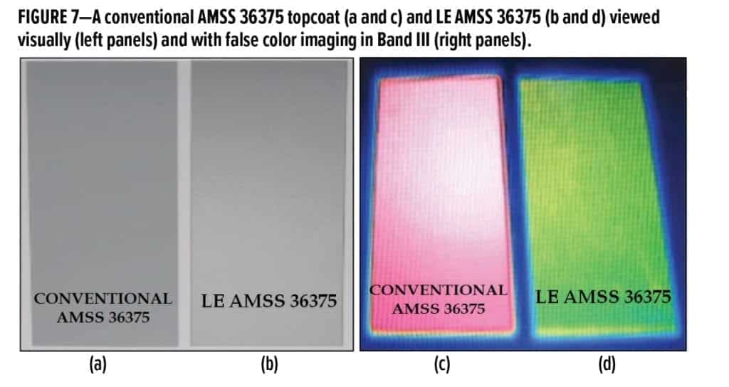
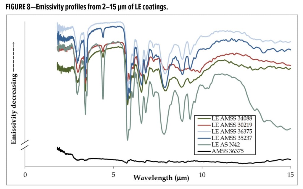
Although the LE AMSS 36375 coating was formulated to present a color appearance similar to the conventional AMSS 36375 coating, when the two panels were heated together at 100°C and then viewed through a thermal camera (Figure 7), the conventional AMSS 36375 coating appeared hot (red) while the LE AMSS 36375 coating appeared much cooler (green). The LE properties of each coating were confirmed by emissivity measurements (Figure 8).
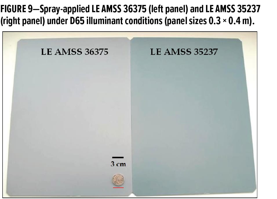
The quality of the topcoat and the ease of application by spray of the LE coatings was demonstrated when applied over large areas (Figure 9). The resultant cured coatings showed a consistent uniform appearance free from grit and with no indication of banding. Further spray application tests were conducted on 1.2 m x 1.2 m sized panels with similarly successful results.
Specification Testing
Coating LE AMSS 36375 was tested against the performance requirements listed in the 85285E and 9001A aircraft topcoat specifications, and results are listed in Tables 8-12. Three additional DST Group tests specific for LE coatings were also undertaken and are denoted by “LE property” in Tables 10-11.
The results of testing the other LE coatings against their respective topcoat specifications will not be reported in this article.
Composition Properties
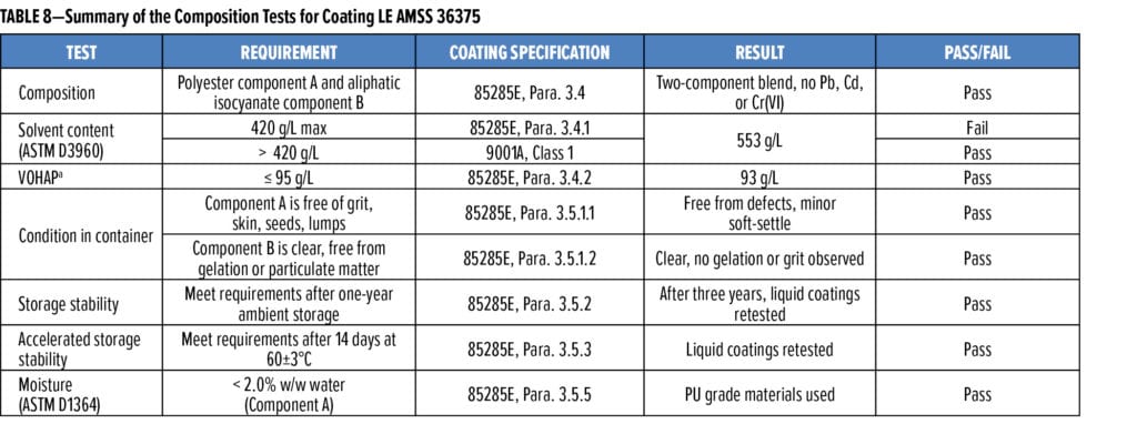
The composition tests for the LE AMSS 36375 coating indicated that all tests in this category conformed to the requirements of 85285E except for the solvent content (Table 8) that did, however, conform to the requirements of 9001A, Type I coatings. A solvent content exceeding 420 g/L was required to assist in reducing the viscosity, imparted by the high molecular weight polyol used in Component A and to ensure good flow and laydown of the TIR-suppressing pigments so that a finish suitable for military equipment could be obtained while providing the required LE properties.
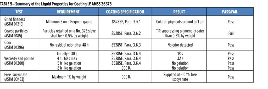
Liquid Properties
The solvency of Component A of LE AMSS 36375 was selected to assist in giving adequate flow while ensuring good drying times for the admixture. This enabled rapid equipment turn-around times during application or repairs. The particle size of the TIR-suppressing pigment was also found to be an important consideration when evaluating the flow of the admixed coating and the quality of the cured films (Table 9). A balance between the particle-size distribution of the TIR-suppressing pigments and coating properties normally expected for a conventional coating is required when formulating LE coatings. Pigment particles too small to provide large changes in LE properties increase the pigment volume concentration (PVC), which can lead to mechanical failure of the coating. Pigment particles too large, while providing better TIR suppression properties, can cause issues during filtering and spray application. A compromise between LE properties and coating integrity was found by formulating with TIR-suppressing pigments that have a particle size distribution containing a fraction larger than 45 mm that are subsequently collected by a #325 sieve. The performance of low-emissivity coatings requires the use of large TIR-suppressing pigments (when compared with conventional colored pigments) that would not normally be used for conventional coatings. Thus, the coarse particle test described in 85285E is not applicable for low-emissivity coatings.
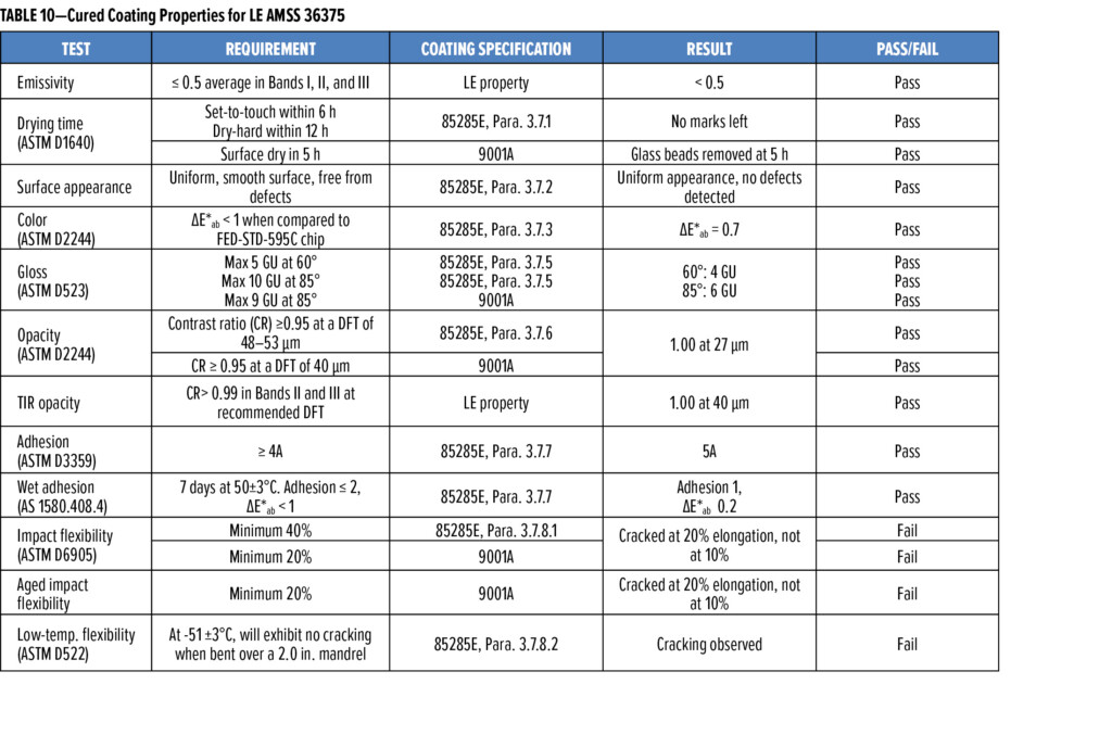
Cured Coating Properties
The cured LE AMSS 36375 coating showed acceptable film properties, such as gloss levels, appropriate for military applications and acceptable wet and dry adhesion to the test substrate (Table 10) in conjunction with suitable LE properties. Properties relating to the flexibility of the coating did not conform to the requirements of 85285E or 9001A. The coating flexibility performance is attributed to the large-sized TIR-suppressing pigments that have large interfaces within the polymer network. These act as weak spots within the film when stress is applied. Evidence to support this assertion was that the Army LE coatings that contain more resin did not show cracking at 20% elongation during impact flexibility testing. Also, the unpigmented cured polymer used for the LE coatings was found to be flexible.
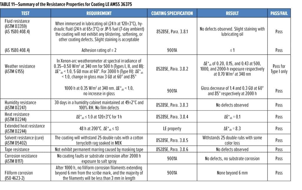
Resistance Properties
Excellent results were obtained for resistance to hydrocarbon-based liquids such as hydraulic fluid, lubricating oil, and aviation fuel. Resistance to sources of thermal and UV radiation was also demonstrated (Table 11). Some coating damage was noted on interaction with MEK. This did not affect the LE performance of the coating.
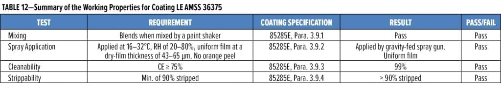
Working Properties
The admixed LE AMSS 36375 liquid showed mixing and spraying properties suitable for application by a gravity-fed spray gun (Table 12) as all results in this category conform to 85285E.
Importantly, the cured LE AMSS 36375 coating displayed excellent cleanability. The utility of LE coatings is in the suppression of TIR. If the LE coating were to be permanently contaminated by high-emissivity materials during use, it would lose the attribute to deliver LE properties. Therefore, the CE of the LE coating is critically important. The conventional AMSS 36375 and LE AMSS 36375 were found to have a CE of 95% and 99%, respectively. This CE was confirmed by examining the emissivity of the coating before and after staining. The high CE performance of LE AMSS 36375 is shown in Figure 10. This cleanability result was maintained when tested after three consecutive soiling/cleaning cycles.
LE-Specific Testing
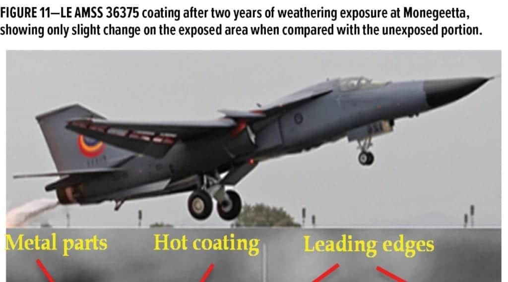
The exterior weathering performance of the LE AMSS 36375 topcoat was compared with that of a conventional aerospace coating. Exterior weathering over two years indicated that the LE AMSS 36375 coating had good performance (Figure 11). After two years of exposure at Monegeetta, the wiped side of the panel showed a DE*ab value of 1.6 units and a gloss change of only 0.5 GU at 60°. The major contributor to DE*ab was a loss of blue with a Db* of 1.5 units. By this time, the DE*ab of the conventional AMSS 36375 was 0.8. For both coatings, practically no chalking was observed.
The thermal stability of LE AMSS 36375 was shown to be better than the conventional AMSS 36375. When subjected to the long-term heat test (Figure 12), LE AMSS 36375 showed some yellowing with a DE*ab of 8.3, while the conventional AMSS 36375 had changed to a brown color with a DE*ab of 19.8.
Discussion
Results Conforming to the Requirements 85285E and 9001A
An evaluation of the LE AMSS 36375 topcoat against 85285E and 9001A found that most of the specification requirements were met. This was an excellent result for a coating that was formulated with the primary purpose of suppressing TIR emissions from hotspots on military equipment.
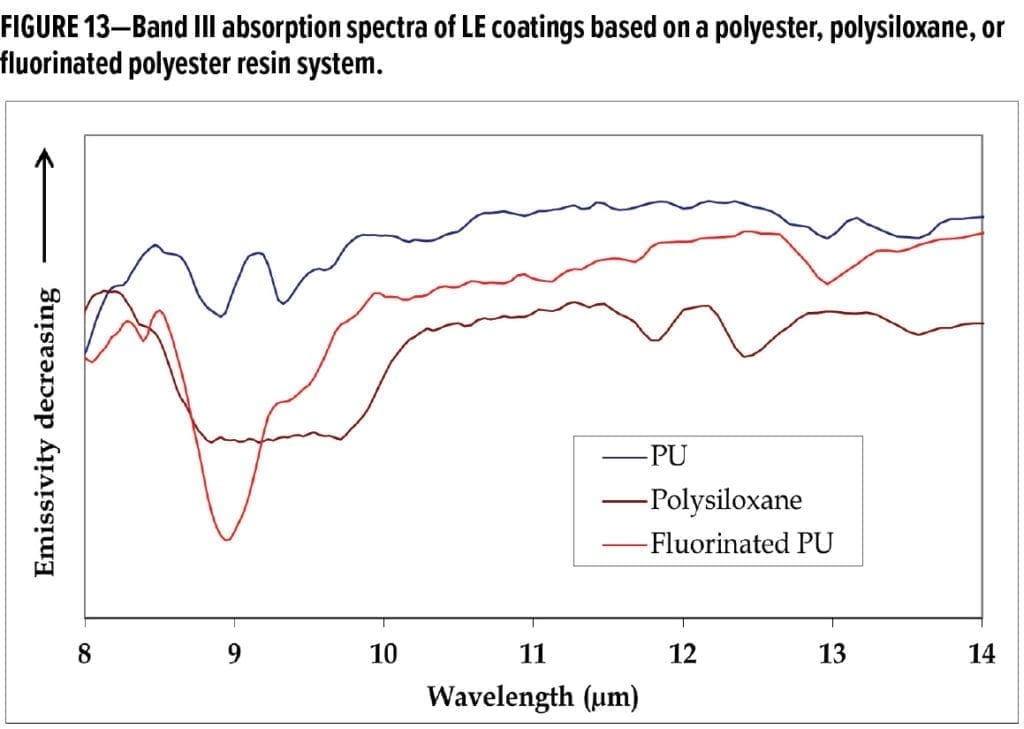
Much of this success is attributed to the polyurethane (PU) system chosen for the LE coatings. The UVA-accelerated weathering performance demonstrated that the polyester resin and aliphatic isocyanate combination chosen for LE coatings produced a durable PU coating. To extend the weathering durability of a coating, one formulating approach could be to use a fluorinated PU or polysiloxane resin. These resins are proven to have better exterior durability than two-pack PUs employing polyesters or conventional acrylics.51,52 When formulating LE coatings, the absorption of TIR by the binder, pigments, and additives in the bands of interest must be minimized. Both fluorinated PU and polysiloxane resins will adversely affect performance of LE coatings in Band III when compared with the chosen PU system due to the presence of either carbon-fluorine or silicon-oxygen bonds in its polymer backbones. These functionalities produce unwanted absorption bands from 8–10 mm (Figure 13). PUs based on polyesters tend to have more adsorption at wavelengths from 5–7 mm that are located in the opaque waveband between Bands II and III where water and carbon dioxide absorb,53 which is a positive attribute for low-emissivity coatings operating at temperatures <250°C. In this respect, the operational performance as an LE coating superseded the consideration for extended durability.
The use of a PU binder limits the operational performance of these LE coatings to a maximum temperature of 250°C before polymer degradation and coating breakdown occurs. This restricts the application of these formulated LE coatings over hotspots, where the majority of the TIR emissions in Bands II and III are generated. LE coatings tailored for Band I suppression could be formulated by using a high-temperature-resistant silicone resin not presented in this article.
Results Not Conforming to the Requirements 85285E and 9001A
An evaluation of the LE AMSS 36375 topcoat against the 85285E and 9001A specifications found that some requirements were not met. An option would be to write a new specification for LE coatings that reduces the requirements to match their properties. While this is possible, the nonconformances against the specifications may point towards formulation changes that can be investigated in future work.
In formulating the LE coating, the VOC limit of 420 g/L specified in 85285E was exceeded but passed the 9001A requirement when classified as a Class 1 conventional coating.
The need for a high-solids LE coating was not the primary target of this work. LE coatings are required for application over hotspots on defense platforms. These areas are generally small in size; therefore, the overall amount of VOC release will be small compared with a conventional coating applied onto large areas. Should a low-VOC formulation of an LE coating be required in the future, a number of options could be explored. These include, in order of difficulty, a replacement for the current organic solvents with resin-compatible VOC-exempt solvents; a change in use of the current polyol to a lower molecular weight version with lower viscosity; or move to waterborne technology that uses minimal organic solvent.
An irradiance of 0.70 W/m2/nm at 340 nm was used in the extended UVA durability testing for the LE AMSS 36375 coating. This is not the irradiance described in the requirements of the 85285E (0.35–0.50 W/m2/nm at 340 nm) or 9001A (0.35 W/m2/nm at 340 nm) specifications. The irradiance of 0.35 W/m2/nm at 340 nm and duration of exposure described in 9001A was determined not to be demanding enough to simulate the severe Australian climatic conditions experienced by coatings in ADF service. Before the inclusion in 2014 of a Type IV coating in 85285E, the 3000-h requirement for extended durability for Type IV coatings (at an irradiance of 0.35-0.50 W/m2 at 340 nm) was not required. By that time, the accelerated weathering for LE AMSS 36375 over a 2000-h period had been completed at an irradiance of 0.70 W/m2 at 340 nm. It could be argued that 2000 h of exposure at an irradiance of 0.70 W/m2 (a total energy input of 5.04 MJ at 340 nm) exceeds that of a 3000-h exposure at 0.35 W/m2 (the lower limit of the 85285E test requirement) with a total energy input of 3.78 MJ at 340 nm). A counter argument is that the exposure has a temporal requirement, not just total energy adsorbed by the coating, and the test must be repeated for the full 3000 h at the correct irradiance. Until that is completed, the LE coating will be tentatively classified as conforming to 9001A, but only as a conformance against a Type I coating described in 85285E.
The 40% elongation requirement in 85285E is difficult to meet. The achieved coating flexibility performance of 10% elongation for the LE AMSS 36375 coating is attributed to the large-sized TIR-suppressing pigments that have large interfaces and act as weak spots within the film when stress is applied. A 10% elongation is considered reasonable for a coating containing both TIR-suppressing pigments that provide the required LE properties and a polymer system with chemical resistance against hydrocarbon fluids. Therefore, there should be no hesitation in using these coatings on military platforms. Conventional coatings based on both solvent and waterborne systems tested for impact flexibility only achieved 20% elongation while displaying chemical-resistance properties. Those that did pass the 40% elongation requirement showed lower chemical resistance performance.54 A more flexible polyester resin could be investigated during future work. For current purposes, the use of LE coatings on areas of military platforms where extreme flexibility is required should be avoided to prevent water ingress that leads to corrosion if a crack in the coating were to occur.
LE-Specific Properties
The emissivity of the LE coatings was formulated to be ≤ 0.5 in Bands I, II, and III to demonstrate the utility of these coatings to suppress TIR emissions when compared with a conventional coating. The emissivity of these coatings can be adjusted to suit the needs of the operating environment. Coating opacity with a CR of 0.99 was achieved throughout the TIR wavelength ranges, and this ensured that full TIR radiation suppression by the LE coating was obtained.
The extended heat resistance testing of both the LE AMSS 36375 and conventional AMSS 36375 coatings showed that the LE AMSS 36375 coating exhibited less color change than the conventional AMSS 36375 coating. This provides evidence that the PU selected for the LE coatings either develops less colored chromophores on heating, or that the color pigments selected for the LE coatings are more thermally stable and do not change color on heating when compared with the conventional AMSS 36375. If required, the thermal stability of LE AMSS 36375 could be further improved by the addition of an antioxidant, but this would decrease the LE performance due to its high-emissivity composition.
Conclusion
DST Group LE coatings with five different visual camouflage colors designed to have an emissivity on average of ≤ 0.5 in Bands I, II, and III were formulated to suppress TIR emissions from military platforms. These coatings showed excellent color and gloss retention under accelerated UVA weathering conditions. Qualification testing of the LE AMSS 36375 coating to the requirements of the military topcoat specifications MIL-PRF-85285E and DEF(AUST) 9001A found that the majority of the results conform to the requirements of these specifications. The LE AMSS 36375 coating was found to have comparable exterior weathering performance to that of a conventional AMSS 36375 coating after two years in a temperate climate. The cleanability of the LE AMSS 36375 coating against soiling, which is critical to LE performance, was excellent.
Acknowledgments
The author wishes to thank Dr. Christopher J. Lyons, Mr. Stefan K. Danek and Mr. Gary Mathys, all of DST Group, for assistance with this project.
References
- The DOD Dictionary of Military and Associated Terms (JCS PUB 1-02), Department of Defence, United States of America, 1989.
- AMS-STD-595C, Aerospace Material Specification: Colors Used in Government Procurement, Revision A, SAE International, 2017.
- Australian Standard AS2700, Color Standards for General Purposes, Standards Australia, SAI Global, 2011.
- Brady, R.F. and Wake, L.V., “Principles and Formulations for Organic Coatings with Tailored Infrared Properties,” Prog. Org. Coat., 20, 1-25 (1992).
- “How Does Night Vision Work,” ATN Corporation; accessed August 1, 2019 at: https://www.atncorp.com/hownightvisionworks.
- ISO 20473: 2007E, Optics and Photonics—Spectral Bands, International Organization for Standardization, Geneva, Switzerland, 2007.
- CIE S 017/E: 2011, CIE Standard ILV: International Lighting Vocabulary, International Commission on Illumination CIE Central Bureau, Vienna, Austria, 2011.
- Rogalski, A., Infrared Detectors, 2nd ed., Boca Raton: CRC Press, 2011.
- Elion, G.R. and Elion, H.A., Electro-Optics Handbook, Vol. 3, New York: Marcel Dekker Inc., 1974.
- Halliday, D. and Resnick, R., Fundamentals of Physics, 3rd ed. (ext.), New York: John Wiley & Sons, 1998.
- Quinn, T. J., Monographs in Physical Measurement: Temperature, London: Academic Press, 1984.
- ASTM G173-03, Standard Tables for Reference Solar Spectral Irradiances: Direct Normal and Hemispherical on 37° Tilted Surface, ASTM International, West Conshohocken, PA, 2012.
- Phillips, K.J.H., Guide to the Sun, London: Cambridge University Press, 1995.
- Mahulikar, S.P., Potnuru, S.K., and Rao, G.A., “Study of Sunshine, Skyshine, and Earthshine for Aircraft Infrared Detection,” J. Opt. A Pure Appl. Opt., 11 (4): 045703 (2009).
- Jacobs, P.A., Thermal Infrared Characterization of Ground Targets and Backgrounds, 2nd ed., Tutorial Texts in Optical Engineering, Volume TT70, Washington: SPIE Press, 2006.
- Infrared Spectra of Carbon Dioxide and Water, National Institute of Standards and Technology, NIST Chemistry WebBook, SRD69, U.S. Department of Commerce; accessed August 1, 2019 at: https://webbook.nist.gov/chemistry/.
- Sabins, F.F., Remote Sensing: Principles and Interpretation, 2nd ed., New York: W.H Freeman and Company, 1986.
- Pollock, D.H., Accetta, J.S., and Shumaker, D.L. (Eds.), The Infrared and Electro-Optical Systems Handbook: Volume 7, Countermeasure Systems, Washington: SPIE Optical Engineering Press. 1993.
- Image of a General Dynamics RF-111C Aardvark © Jeff Gilbert—JGPhotographics; accessed August 1, 2019 at: https://www.airliners.net/photo/Australia—Air/General-Dynamics-RF-111C/1804190/L/.
- AIM-9X Sidewinder Missile, Infrared-Tracking, Short-Range, Multi-Mission Missile; accessed August 1, 2019 at: https://www.raytheon.com/capabilities/products/aim-9x.
- Stinger Weapon System, Lightweight, Portable Air Defense; accessed August 1, 2019 at: https://www.raytheon.com/capabilities/products/stinger/.
- Russia shows Verba Manportable Missile System, IHS Janes Defence Weekly, May 10 2018; accessed August 1, 2019 at: https://www.janes.com/article/79960/russia-shows-verba-manportable-missile-system-sofex18d3.
- Haulman, D.L., “USAF Manned Aircraft Combat Losses 1990-2002,” Air Force Historical Research Agency, 2002.
- Nordeen, L.O., Air Warfare in the Missile Age, 2nd ed., Washington DC: Smithsonian Institution Press, 2014.
- Banken, G.J., Cornette, W.M., Gleason, K.M., and Keith, M., Investigation of Infrared Characteristics of Three Generic Nozzle Concepts. Proc. AIAA/SAE/ASME 16th Joint Propulsion Conference, AIAA paper no. 80–1160, Reston, VA, USA: AIAA Inc. (1980).
- Moore, M.D. and Marques, E.C., “Turbofan Engine with Variable Exhaust Cooling,” Boeing Co., U.S. Patent 9,574,518B2, 2014-06-02.
- Gray, C.N. and Shayeson, M.W., “Aircraft Fuel Heat Sink Utilization,” Technical Report AFAPLTR-73-5I, General Electric (1973).
- Flare (countermeasure); accessed August 1, 2019 at: https://en.wikipedia.org/wiki/Flare_(countermeasure)#/media/File:391st_Expeditionary_Fighter_Squadron_-_F-15E.jpg by Tech. Sgt. Cecilio Ricardo (U.S. Air Force).
- Koch, E.C., “Pyrotechnic Countermeasures: II. Advanced Aerial Infrared Countermeasures,” Propellants, Explosives, Pyrotechnics, 31 (1), 3-19 (2006).
- Goldberg, S., “Infrared Countermeasures: The Systems that Cool the Threat from Heat-Seeking Missiles,” Air & Space Smithsonian (2003); accessed August 1, 2019 at: https://www.airspacemag.com/how-things-work/infrared-countermeasures-4739633.
- Caplan, W., “Requirements for Laser Countermeasures Against Imaging Seekers,” Proc. Vol. 9251, Technologies for Optical Countermeasures XI; and High-Power Lasers 2014: Technology and Systems; 925103 SPIE Security and Defence, Amsterdam, Netherlands, 2014.
- Holmann, J.P., Heat Transfer, 9th ed., New York: McGrawHill, 2002.
- ISO 9288:1989: Thermal Insulation—Heat Transfer by Radiation—Physical Quantities and Definitions, International Organization for Standardization, 1989.
- Infrared Thermometer Emissivity Tables; accessed August 1, 2019 at: https://documents.scigiene.com/content/documents/428_InfraredThermometerEmissivitytablesrev.pdf.
- Singham, J.R., “Tables of Emissivity of Surfaces,” Int. J. Heat Mass Trans., 5, 67-76 (1962).
- MIL-PRF-85285E, Performance Specification, Coating: Polyurethane, Aircraft and Support Equipment, Department of Defense, United States of America, 2012.
- DEF(AUST) 9001A, ADF Aircraft Epoxy/Polyurethane Paint Coating System, Australian Defence Standard, Commonwealth of Australia, 2009.
- APAS Specification 0502 v2, Disruptive Pattern Camouflage Polyurethane Finishing System for Vehicles & Equipment, CSIRO, 2007.
- APAS Specification AP-S0501 v3, Low Solar Absorbing, Color Stable Exterior Topside Paint for Navy Vessels, CSIRO, 2014.
- MIL-PRF-23377K, Performance Specification Primer Coatings: Epoxy High Solids, Department of Defense, United States of America, 2005.
- MIL-PRF-85285D, Performance Specification, Coating: Polyurethane, Aircraft and Support Equipment, Department of Defense, United States of America, 2002.
- ASTM D2244–16, Standard Practice for Calculation of Color Tolerances and Color Differences from Instrumentally Measured Color Coordinates, ASTM International, West Conshohocken, PA, 2016.
- ASTM International, accessed August 1, 2019 at: www.astm.org.
- Standards Australia, accessed August 1, 2019 at: https://www.standards.org.au/.
- FED-SPECS, accessed August 1, 2019 at: https://www.estore.fed-std-595.com/.
- ASTM G 155-05a, Standard Practice of Operating Xenon Arc Light Apparatus for Exposure of Non-metallic Materials, ASTM International, West Conshohocken, PA, 2005.
- AS/NZS 1580.481.1.11:1998 (R2013), Paints and Related Materials—Methods of Test—Coatings—Exposed to Weathering—Degree of Chalking, Standards Australia.
- Howell, J.R., Siegel, R., and Pinar Menguc, M., Thermal Radiation Heat Transfer, 5th ed., Boca Raton: CRC Press, 2011.
- MIL-PRF-83283D, Performance Specification, Hydraulic Fluid, Fire Resistant, Synthetic Hydrocarbon Base, Metric, NATO Code Number H-537, Department of Defense, United States of America, 1997.
- MIL-PRF-85570D, Performance Specification, Cleaning Compounds, Aircraft, Exterior, Department of Defense, United States of America, 2002.
- Mowrer, N.R., Foscante, R.E., and Rojas, L., “Epoxy-
Polysiloxane Copolymer Composition,” Ameron International Corporation, U.S. Patent 5,804,616, 1997. - Yang, F., et al., “Degradation of Low Gloss Polyurethane Aircraft Coatings under UV and Prohesion Alternating Exposures,” Polym. Degrad. Stab., 80 (1), 51-58 (2003).
- Colthup, N.B., “Spectra-Structure Correlations in the Infra-Red Region,” J. Opt. Soc. Am., 40 (6), 397-400 (1950).
- Lyons, C.J., “A Two-Pack Waterborne Polyurethane Topcoat for Military Aircraft,” CoatingsTech, 14, (6) 38-52 (2017).
CoatingsTech | Vol. 17, No. 4 | April 2020