
By Clifford K. Schoff, Schoff Associates
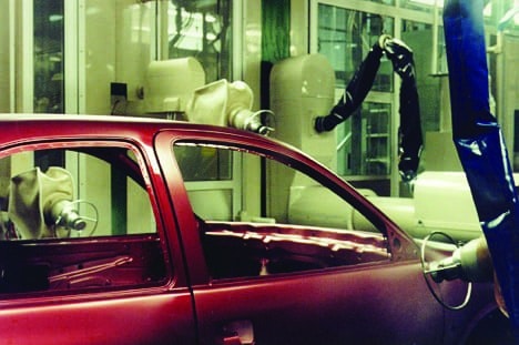
Spraying is the worst possible way to apply automotive coatings if minimization of surface defects is desired, but it is the only way to obtain the gloss, color effects, and outstanding appearance that car buyers demand. This article surveys some of the defects that automotive coatings experience when they are applied. Craters undoubtedly are the most infamous and cause the greatest panic in the auto plant, but a number of other defects can occur. All defects hurt appearance and some also can interfere with the corrosion or weathering protection aspects of the coatings. Repairing of defects can lead to more problems, so the best strategy is to prevent them from occurring.
SURFACE TENSION-RELATED DEFECTS
Many of the common day-to-day defects seen on car bodies are surface tension driven. These include craters, dewetting, telegraphing, picture framing (fat edges), and poor edge coverage.
Craters
Nearly all coatings people are familiar with craters, but they may not know much about them. Craters are caused by low surface tension contamination that is on the substrate being painted, is in the paint, or falls on the paint. This produces a surface tension gradient that causes flow away from the low surface tension area, resulting in a circular low spot (see Figure 1 for an example). Shallow craters often can be polished out, but deep ones require sanding and repainting. Craters vary in size and appearance, even from a given contaminant. The majority of cases that I have encountered in auto plants have involved contaminants falling on the wet coating during or soon after application, but the other possible causes always must be considered. Unfortunately, it is difficult to identify contaminants and their source. Rigorous inspections of paint shops have turned up sources such as poor substrate cleaning, oily overhead chains, smoking ovens, oil in the compressed air, and dirty paint booths, but often there is no obvious cause. If the contaminant can be identified, then there is a good chance that its source also can be found. However, contaminant identification is anything but easy and usually requires examination of individual craters by optical microscopy and analysis by techniques such as scanning electron microscopy, Fourier transform infrared microscopy (FTIR), and/or infrared microscopy. Unfortunately, when the coating is baked, any volatile contaminant such as a hydrocarbon or silicone oil is liable to be driven off in the oven This leaves nothing to analyze or such a miniscule amount that it takes expensive techniques like x-ray photoelectron spectroscopy (XPS or ESCA) or secondary ion mass spectrometry (SIMS) to identify it.
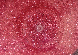
FIGURE 1—Basecoat crater due to contaminant in the primer.
Dewetting
Other surface tension-related defects include dewetting, telegraphing, and picture framing. Let’s begin with dewetting. Although spraying usually is effective at force wetting of the surface of a substrate or undercoat and spreading a film across it, during or shortly after application there may be a pulling back or retracting of the film. This behavior is called dewetting or crawling. The paint appears to initially wet the surface, but cannot sustain this contact and pulls away. Dewetting also can produce beads of paint, islands, craters, or pinholes (see Figure 2).
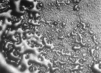
FIGURE 2—Example of severe dewetting.
The defect usually is due to dirty or otherwise contaminated surfaces. It is critical to ensure good cleaning and pretreatment of metals and power washing and solvent wiping of plastic parts. It is equally important to keep surfaces clean after these processes, especially when car bodies or parts are stored for even a day or two (such as over a weekend) before the painting process is completed.
There are tests to determine whether a surface is wettable. The standard method for doing this is the measurement of contact angles (see ASTM standards D7334 and D7490) where a low angle (5–30°) indicates adequate wettability and a high one (> 45°) signals possible problems such as contamination. However, contact angle measurements require specialized equipment and are not practical in the field.
There are several simpler wetting/dewetting tests that can be used. ASTM D7541 describes cotton swab, marking pen, and drawdown techniques that simulate the application of a film. The swab and marking pen techniques are simple and rapid and are particularly useful for testing in the field or on curved, irregular, or porous surfaces where contact angles cannot be measured. The swab test involves applying a series of solvents of known surface tension onto the substrate with cotton swabs and observing whether the strip of solvent stays in place or dewets and crawls. The breakpoint between wetting and dewetting provides what is called the critical surface tension of dewetting. The commercially available marking pens work in the same way. A paint with a surface tension below the dewetting critical surface tension of a substrate will wet that substrate unless there is subsequent contamination.
Telegraphing
Telegraphing is a defect that involves the reproduction of surface features on an undercoat or substrate by the coating applied over it (Figure 3). Most examples that I have seen were where a basecoat made fingerprints, wipe marks, detergent residues and/or sand scratches on the primer more obvious instead of covering them up.
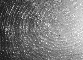
FIGURE 3—Magnification of telegraphing of a fingerprint. The surface should be smooth.
The main cause of this defect is flow due to surface tension: flow away from residues such as finger oils and sanding dirt or flow away from sharp edges of sand scratches. Aluminum flakes in automotive metallic coatings have been known to line up along sand scratches or wipe marks, leaving silvery streaks noticeable from a considerable distance.
Sanding telegraphing (also called sand mar) is where soak-in of paint into sanded areas causes changes in gloss, color, or flake orientation in coatings with aluminum or mica flakes. Wetting and flow on sanded areas are affected by the roughness, porosity, and the increased wettability of the abraded surface. Sand mar and telegraphing of sand scratches often have responded to reducing damage to the primer by the use of finer sandpaper, sanding smaller areas, and sanding with less force.
Prevention of primer defects so that sanding is unnecessary is the ultimate solution, but a difficult one to achieve. The new solventborne and waterborne three-wet processes (primer/basecoat in one application) would seem to offer relief from telegraphing involving primers. However, I have seen rough three-wet primer layers that could affect the basecoat layer topography and, possibly, the overall appearance.
Picture Framing (Fat Edge) and Poor Edge Coverage
Picture framing (fat edge) and poor edge coverage are other problems caused by surface tension driven flow (see diagram in Figure 4). Picture framing is most common along door jambs, under windows, and along other edges of an auto or truck body. In some cases, it may be from electrostatic wrap or other spraying effects, but it usually is caused by surface tension gradients during baking.
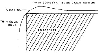
FIGURE 4—Diagram showing a thin edge (poor coverage) and a fat edge.
Solvents tend to evaporate more rapidly from edges. Those regions become richer in higher surface tension coating vehicle (and may experience evaporative cooling which further raises surface tension) and a surface tension gradient is set up which causes flow of material to the edges. Sometimes the bead that forms is back from the edge. In this case, the edge probably has heated up faster on baking than the rest of the part or panel. This initially lowers the surface tension and gives a gradient that causes flow away from the edge, producing an offset bead.
A different, but related, defect is flow away from sharp edges during the bake so that a cut edge or sharp style line will end up with little or no coverage on it (also shown in Figure 4). This is because surface tension forces work to minimize the surface area of the coating. This used to be a serious problem with ED primers, which produced good edge coverage on deposition, but flow on baking resulted in very thin or no coverage on sharp edges. This was noticeable as “blue edge” and sometimes gave corrosion problems. Adding more pigment prevented flow away from the edge, but gave rough, ugly coatings. Most current formulations give edge coverage and smooth coatings.
Prevention
Not surprisingly, prevention of surface tension driven defects requires good control of surface tension during application and during the flash and bake.
This begins with the development of paint formulas that contain components such as surface active additives and solvents that give the wet paint a surface that is homogeneous with low surface tension. This maximizes wetting of undercoats and minimizes surface tension gradients that might occur due to contamination or temperature differences. It reduces sensitivity to airborne contaminants.
Silicone surfactants are particularly effective in accomplishing this, but they must be used at very low levels or repair or recoatability may not be possible. Silicone oils (linear dimethyl siloxanes and polydimethyl siloxanes) are so highly surface active and mobile that they must be kept away from paint, paint plants, and auto plants. They are notorious for causing plant and equipment contamination as well as adhesion and surface defect problems. Polyether or polyester modified polydimethyl or polymethyl alkyl siloxane surfactants that are added at 0.1–0.3% on total paint and are well dispersed are much more likely to prevent problems rather than cause them. Small amounts of low surface tension solvents such as butanols, 2-ethyl hexanol, and VM&P Naphtha also have been used to lower the surface tensions of liquid coatings. The advantage of solvents as additives is that they evaporate on air drying or baking and are not left behind in the coating as are surfactants.
The other strategy is to raise the low shear viscosity of the paint so that is less apt to dewet when confronted with a less than clean surface, or flow away from a low surface tension contaminant or be affected by temperature differences across the wet surface. This is more likely to produce orange peel (see below), but has been at least a temporary solution to many surface tension related plant problems. The best way to prevent or reduce these defects is to develop a combination of surface tension control and rheology optimization. Unfortunately, this is very difficult to design into a paint and usually takes much trial and error experimentation.
OTHER FLOW DEFECTS
In addition to defects caused by surface tension driven flows, there are defects because of gravity driven flow (sagging) and lack of flow and leveling (orange peel).
Sagging
Sagging is an example of too much flow. It is caused by gravity driven flow on vertical surfaces. Automotive topcoat sags may occur, but they are much less common than those that happen in ED primers. The latter usually are caused by run-out, paint that has been trapped in seams, flanges, and inner areas and boils and runs out on baking and produces drips. These defects must be smoothed out by sanding before the basecoat is applied. Sags in automotive topcoats usually are subtle, although very occasionally there will be a drip down a vertical on a deck lid, under the cut-out for the gas cap, or along a door jamb. Often, the defect only is noticeable if there are fine pops or pinholes that occur in the thick area. Spray application of paint often produces a pattern of droplets and the “bumps” may form very small sags (microsags) on vertical surfaces, but will flow out on horizontal surfaces. This is one reason why verticals on automobiles such as doors and verticals on deck lids (“waterfalls”) look rough in comparison to hoods, roofs, and deck lid horizontals. Another reason is that auto companies are so concerned about sagging that paint applied to verticals often has a higher viscosity, which prevents sag, but also interferes with leveling.
When sagging occurs on application, it is called cold sag. When it occurs in the oven, not surprisingly, it is called hot sag. The latter problem became more common as the industry went to high solids coatings with low molecular weight polymers and oligomers that flow and flow and flow at elevated temperatures even after all the solvent has gone. Fortunately, it is not necessary to stop downward flow completely to prevent sag. In fact, some flow is needed for leveling. If the sagging velocity is low enough, the paint will dry or cure before noticeable sag will occur.
Sagging can be reduced or prevented by raising the low shear rate viscosity of the paint and/or applying thinner coats of paint. The film viscosity can be raised by using faster solvents or by introducing thickeners or thixotropes. The latter are additives such as fumed silica, treated clays, microgels, and castor oil derivatives that form physical networks. Associative thickeners in waterborne paints serve a similar purpose. Structures form after application to reduce flow and also modify viscosity-temperature behavior to prevent sag in the oven. Unfortunately, they also can prevent flow-out and leveling on horizontal surfaces, so amounts of the additives must be chosen carefully.
Orange Peel
The term orange peel refers to a bumpy coating surface that resembles the surface of an orange. It may be barely noticeable or very obvious. It is not considered a defect if it is not excessive. Excessive is in the eye of the beholder, of course. The Quality Supervisor on the first shift in an auto plant may find the paint jobs on the car bodies to be acceptable. The QS on the next shift may decide that there is too much obvious orange peel and the paint supplier will have to ask for adjustments to the spray parameters. Ultimately, the supplier may need to put a little more solvent in the clearcoat tank to get more flow.
Ironically, a survey of auto customer years ago found that a majority were not unhappy with orange peel. They thought that it meant that there was sufficient paint on the car.
Orange peel normally is due to poor flow-out and leveling of spray droplets, but occasionally is caused by surface tension driven flow (sometimes called sinks and bumps) in the oven. I also have seen a few cases where a rough basecoat produced an orange peel appearance even though the clearcoat surface was smooth (optical illusion?). Orange peel rarely affects gloss, but the bumpy surface can hurt distinctness of image (DOI), another sought-after appearance parameter. This can be seen in Figure 5 where an auto hood with orange peel gives fuzzy, indistinct reflections of the overhead lights.
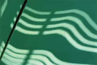
FIGURE 5—Orange peel as seen in the reflection of overhead lamps on
a car hood.
FOREIGN MATERIAL (DIRT)
Surface tension is involved in a great many coatings defects, but there are other causes as well. In my experience, foreign material (let’s just say dirt) is the most common automotive coating defect of all. However, it is something that is of much greater concern to paint manufacturing engineers and customer service people than paint formulators.
Dirt that shows up on or in paint films may include fibers, sanding dust, metal particles (including weld balls from the body shop), oven dirt (condensate and carbonized resin), and general dust and grit. Figure 6 shows a fiber, probably the most common type of coatings dirt. However, relatively few pieces of dirt are so easy to see. Most dirt defects are just bumps and must be cross sectioned to get an idea of what is in the bump. Figure 7 shows an example. Resin gel particles, pigment agglomerates, and paint chips and flakes also may be considered as dirt. There are other defects that resemble dirt such as paint drops, gun spits, and overspray. These and substrate defects, solvent pops, and gassing have been mistaken for dirt many times and have led to much effort spent working on the wrong problem.
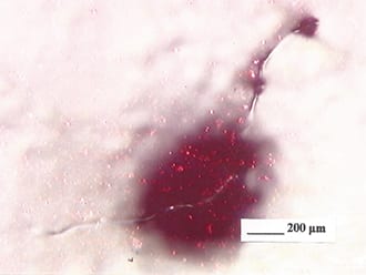
FIGURE 6—A typical piece of dirt in an automotive coating, a fiber.
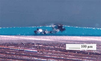
FIGURE 7—Cross section of overspray particles in a clearcoat.
Dirt on auto coating surfaces sometimes can be polished out, but more often leads to sanding, which produces more dirt, and repainting. The latter may be a high bake repair involving painting with the same paint as before and running the body back through the oven or ovens. This tends to decrease chip resistance. For repairs on finished bodies, a low bake repair sometimes is carried out where a catalyzed version of the clearcoat is applied and baked with a heat lamp or heat gun. This has worked well for craters and other small areas, but the surface tends to have poor scratch resistance so larger areas may end up suffering mar and scratch problems in the field.
The paint usually is blamed for dirt problems, but rarely is the culprit. Most dirt comes from the auto plant and may be due to the painting process itself, poor work practices by the operators, bad air filtration, or poor housekeeping. However, it can come from the paint and manufacturers should take great care to prevent dirt or anything that resembles dirt from getting into or forming in the paint. Clean raw materials are essential. Good housekeeping in the paint plant is required and equipment such as tanks, mills, pipes, and hoses must be kept clean. Cleanliness is just as important for cans, drums, totes, and tank wagons and the valves on the latter two. By the same token, most auto factories and their equipment could be kept cleaner than they are and would see less dirt on the car bodies if this were accomplished.
VOLATILE-RELATED DEFECTS
Various volatiles cause another set of defects. Most automotive coatings contain solvents that must come off during the flash or be driven off during the bake. Air may be incorporated into the paint during stirring, pumping, or spraying and be trapped in the final film. After application, cure reactions or volatiles coming from under the coating may introduce bubbles that escape from the film with difficulty such that some are trapped in the coating or blow their way out after the film has formed.
Popping
Popping involves the formation of defects by the blowing out of trapped solvent or other volatiles during baking. The result may be miniature volcanoes, pinholes, craters, dimples, bubbles, or a few of each. The defect is often called solvent popping, but may be due to volatiles from the substrate (also called gassing) or air entrapment. It can be very difficult to distinguish between these mechanisms, although true solvent popping is more likely to involve several or all of the defects listed above. It may be necessary to cross section pop suspects to make certain that they really are pops and to identify the source layer (Figure 8). With the introduction of waterborne basecoats, a new source of popping became apparent. Dehydration of these basecoats can lead to pops in clearcoats applied over them. Too much dehydration (high bake temperature) can produce a porous basecoat, which takes in solvent from the clear, which later blows out resulting in pinholes or pops. Too little dehydration (low bake temperature) leaves water in the basecoat, which then is expelled through the clear producing defects. Sloppy paint application also can lead to popping. Overspray and spits can trap solvent, blow out on baking, or absorb solvent from subsequent coats, then blow out from underneath the second coat. Irregular spraying can give thick spots that pop as do electrostatic spray wrap, fat edges, or sags.
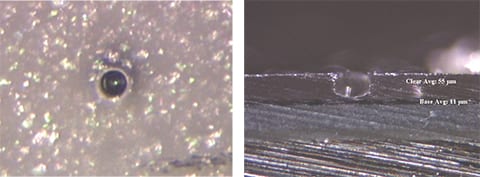
FIGURE 8—A solvent pop in an automotive base/clear (left) and its cross section (right).
Gassing
Gassing defects resemble solvent popping, but are caused by volatiles that originate from the substrate rather than the paint layer. The volatiles force their way up into the wet paint layer as it is baked, resulting in pinholes, volcanoes, and/or bubbles. Subsequent coats rarely seal these defects, particularly if the area has been sanded. Defects occur in the new layer just above the original defects. A cross section would show a series of connected voids through the layers (see Figure 9). Gassing is most common over plastic substrates and zinc coated steel, although I also have seen it occur over aluminum castings (which turned out to unacceptably porous). Gassing over plastics usually is due to air or moisture blowing out of voids near the surface of the plastic as the paint is baked. Many plastics have a thin, but relatively dense “skin” at the surface, but if this skin is missing, has been removed by sanding or itself has voids, there is nothing to prevent volatiles from traveling up into the paint. Some primers are more effective than others at sealing plastics, but the best remedy is rigorous quality control of the plastic parts so that they do not have voids and pinholes at or just below the surface.
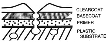
FIGURE 9—Diagram of a cross section of a gassing “pipeline” from a void in the plastic part through the layers of coating.
Another type of gassing called galvanized gassing occurs over electrogalvanized steel and, occasionally, over hot-dipped galvanized. It is due to the release of hydrogen and, possibly, methane from flaps, blisters, or other defects in or under the zinc layer. In a number of cases, the problem has been shown to be due to inadequate cleaning or contamination of the base steel before the zinc layer is applied. However, at other times, no reason or source of the defects has been found.
Galvanized gassing depends entirely on the zinc coated steel, but changing electrodeposition parameters such as solvent level, bath temperature, time, and voltage may help.
Another defect, similar in appearance, called pinhole gassing or rupture, can occur in electrodeposition primers at high deposition voltages. With cationic electrodeposition, the defects are caused by a mechanism that involves electrical discharge followed by hydrogen evolution and water vaporization. Figure 10 shows pinhole gassing in an acrylic cationic electrodeposition coating used on agricultural equipment. Electrical discharge is more likely to occur over zinc coated steels, especially zinc-iron alloys, but it can occur over cold-rolled steel. The defects can be prevented or reduced by lowering and/or ramping or stepping voltage, adding solvent and raising the bath temperature.
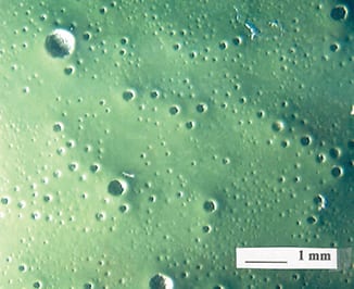
FIGURE 10—Pinhole gassing in an acrylic electrodeposition coating.
Air Entrapment
Air bubbles trapped in paint during manufacture or application can result in bubbles, pinholes, and crater-like defects in the cured film. Usually these defects are difficult to distinguish from solvent pops or craters, so detective work is needed to identify the root cause. Air entrapment rarely is suspected until after solvent popping and substrate gassing have been ruled out as causes.
Bubbles are a possibility wherever there is a stirring or shearing action that can lead to vortexing, turbulence, or cavitation. This can occur in manufacturing processes and in the auto plant itself. I have seen several cases where paint levels in tanks were allowed to drop so far that pumps began sucking air and the paint quickly filled with bubbles. Spraying provides many opportunities for bubble formation. Air may be stirred or dissolved into the paint in the circulation system and remain in the spray droplets. Atomization may cause bubbles, particularly with worn or damaged gun tips or chipped bells. Sometimes doughnut or cup-shaped droplets are produced that trap air and even normal spherical spray particles have been shown to do the same thing, particularly when the droplets are large. Bubbles also may form because of a tendency of the paint to foam.
Most tests for air entrapment involve rapid stirring or shearing (usually with a kitchen blender) of the paint in question as well as a control that does not show the defect and comparing the results. The evaluation can be by eye, weight per gallon measurements, or after spray-outs, but the idea is to see which paint picks up more air. One difference that I have noticed between solvent popping and air entrapment is that spraying thinner and thinner coatings will eventually get rid of popping, but often makes air entrapment more noticeable.
The best way to avoid air entrapment is to prevent the formation of bubbles in the first place. Proper dispersion and mixing practice can reduce air entrapment during manufacture. Correct matching of the batch size with the size of the manufacturing equipment is essential. Proper choice, maintenance, operation, and adjustment of paint application equipment can prevent the trapping of air during application. If bubbles cannot be prevented completely, then keeping the coating surface open longer via slower solvents may allow air to be released before the film sets up.
CONCLUSIONS
Defects and problems do occur while automotive coatings are being applied or soon after, especially during one or another of the bakes. These defects hurt appearance and may compromise the protective ability of the coating. When they occur they must be sanded and repaired, which can lead to additional defects. The best way to fix defects is to prevent them from occurring. Many can be prevented or reduced by control of surface tension and rheology as well as greater cleanliness in paint plants and auto factories. Identifying defects and their causes takes skill and access to specialized tools. The initial examination should be done with an optical microscope, possibly including of cross sections of the defect. It often is necessary to turn to a scanning electron microscope (SEM), Fourier Transform IR and/or an IR microscope for help.
BIBLIOGRAPHY
I have not attempted to give references for the individual defects. Almost all of them may be found in “Coatings Clinics” on the last pages of JCT CoatingsTech over the last 12 years. These articles are being archived in the CoatingsTech area of the new ACA website, and should be available in the near future.
General References
Pierce, P.E. and Schoff, C.K., “Coating Film Defects,” 2nd Edition, Federation Series on Coatings Technology, Blue Bell, PA, 1994.
Schoff, C.K., “Surface Defects: Diagnosis and Cure,” J. Coat. Technol., 71 (88), 56-73 (1999).
Surface Flows
Fink-Jensen, P., Färg och Lack, 8, 5-14, 39-42 (1962); Farbe Lack, 68, 155-162 (1962).
Bierwagen, G., Prog. Org. Coat., 3, 110-113 (1975).
Bierwagen, G., Prog. Org. Coat., 19, 59-68 (1991).
Schoff, C.K., “Rheology of Melts and Solutions Part 2: Viscoelasticity, Temperature and Surface Flow,” JCT CoatingsTech, 4 (9), 86-90 (2007).
Wetting and Dewetting
Schoff, C.K., “Wettability Phenomena and Coatings,” in Schrader, M.E., Loeb, G. (Ed.), Modern Approaches to Wettability: Theory and Applications, pp 375-395. Plenum Press, New York 1992.